|
|
| Line 1: |
Line 1: |
| | {{TOCright}} | | {{TOCright}} |
| | | | |
| − | '''Rich Rudman of [http://www.manzanitamicro.com manzanitamicro], [[User:Rjf|Ryan]], and [[PriusBlue]],''' are working on a [[Prius PHEV]] implementation using an upgraded PFC-30 as a DC-DC converter and charger, and Rich is hoping to develop and offer conversion kits. | + | '''Rich Rudman of [http://www.manzanitamicro.com manzanitamicro], [[User:Rjf|Ryan]], and [[PriusBlue]],''' are working on a [[Prius PHEV]] implementation using an upgraded PFC-30 as a DC-DC converter and charger, and Rich is hoping to develop and offer conversion kits. Find out more about the [[PiPrius conversion process]]. |
| | * [[Prius PHEV#PFC Based]] | | * [[Prius PHEV#PFC Based]] |
| | ** [[Prius PHEV Battery Options#PFC Based]] | | ** [[Prius PHEV Battery Options#PFC Based]] |
| Line 54: |
Line 54: |
| | | | |
| | ==Conversion Procedures== | | ==Conversion Procedures== |
| − | There are a number of tasks to be completed in order for the entire system to function properly. Those tasks are covered in the following subsections of the Conversion Procedures. These instructions are currently under development and may not yet be complete.
| + | See: [[PiPrius conversion process]] |
| | | | |
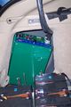
| − | ===CAN-View & EV Mode Button===
| + | ==References== |
| − | Installing the [[CAN-View]] and [[Prius EV Mode Button]] both involve disassembling the same areas of the Prius so will be covered here at the same time.
| |
| − | | |
| − | # Disassemble the dashboard.
| |
| − | ## Remove the bottom cover of steering column
| |
| − | ### Releasing the steering wheel adjustment handle and removing the silver screw.
| |
| − | ### Turn steering wheel 90 degrees to right and left to remove black screws on each side.
| |
| − | ### Remove the lower cover by carefully pulling down on lower half.
| |
| − | ## Disconnect the headlamp flasher plug on left side of steering column.
| |
| − | ### Remove plugs cover by unlocking two side tabs/clips.
| |
| − | ### Remove 3 unused connector pins ''using a jeweler's screwdriver to disengage and slide them out''.
| |
| − | ### Optionally to use the headlamp flasher circuit as an EV Mode button:
| |
| − | #### <font color=darkblue>Solder ''some length??'' of black wire to a new pin and use it to replace:
| |
| − | #### The '''??????''' wire to preserve day time flashing function, will disable night time flashing. ''Preferred''
| |
| − | #### The '''purple''' wire to preserve night time flashing function, will disable day time flashing.
| |
| − | #### Route new black wire over or under steering column towards passenger side of dash.</font>
| |
| − | ### Snap the cover back onto the flasher plug and reinsert into switch.
| |
| − | ### Reassemble steering column, be sure everything is aligned properly.
| |
| − | ## Remove lower glove box by squeezing the inside sides together to lower box below catches, then unclip the small hydraulic piston from right side. Lower box until the lower joints detach from dash.
| |
| − | ## Remove passenger side silver air vent cover by pulling out from the bottom first. Next remove the small interior colored piece just below the vent piece by pulling straight out.
| |
| − | ## If installing CAN-View Without Navigation:
| |
| − | ### <font color=darkblue>Remove drivers side air vent cover.
| |
| − | ### Remove lower center console hump with 12v lighter power socket.
| |
| − | ### Remove air vent at right side of MFD screen.
| |
| − | ### Remove lower drivers side dash panel.
| |
| − | ### Remove lower dash key fob panel.
| |
| − | ### Remove drivers side dash.
| |
| − | ### Remove upper drivers side dash panel with power button.
| |
| − | ### Remove air vent at left side of MFD screen with shift lever.
| |
| − | ### Remove 10mm bolts, one on each side of MFD screen.
| |
| − | ### Attach CAN-View video cable to [[MFD]], run cable out directly behind screen.
| |
| − | ### Tap grey OEM wire for 12v power'', top row 2nd from the left.''
| |
| − | ### Test, then reassemble center and drivers side of dash.</font>
| |
| − | ## If installing CAN-View With Navigation:
| |
| − | ### <font color=darkblue>Route OBDII Cable down drivers side of car.
| |
| − | ### Connect CAN-View video cables to navigation unit.
| |
| − | ### Tap grey OEM wire for 12v power.
| |
| − | ### Test and attach above and to rear of navigation unit.</font>
| |
| − | ## Solder new pin to ''some length??'' of black wire, ''and optionally the black wire which connects to the headlamp flasher.''
| |
| − | ## Install pin with black wire(s) to ev-mode button location in HV ECU ''H14#27''.
| |
| − | ### The HV ECU is the one closest the exterior of the car with grey plugs.
| |
| − | ### H14 is the lowest of the four connectors.
| |
| − | ### Pin #27 is located on the most interior (broken into three segments) row, the second from the bottom left corner, in the only open location between two red wires.
| |
| − | ### Using a jeweler's screwdriver raise the white terminal retainer, fully insert the new pin, and re-compress the retainer.
| |
| − | ## Route CAN-View OBDII cable to OBDII port located above drivers right knee.
| |
| − | ## Route all wires (CAN, Video, black EV Mode) under passenger side door trim exiting under hole in carpet below passenger seat.
| |
| − | ## ''Also route relay cable from below passenger seat under rear passenger side door trim towards rear of car.''
| |
| − | ## Reassemble passenger side of dash and door trim.
| |
| − | # Connect all wires to CAN-View
| |
| − | # Configure CAN-View'', should be preconfigured''.
| |
| − | ## RL1 = '''EV-Mode''' Button trigger
| |
| − | ## RL2 = ''? Voltage dither ?''
| |
| − | ## RL3 = ''? Regen mode ? ''
| |
| − | ## RL4 = '''Stock / PHEV''' mode selection
| |
| − | ## RL5 =
| |
| − | ## RL6 =
| |
| − | | |
| − | See also:
| |
| − | * [http://www.calcars.org/prius-evbutton-install.pdf prius-evbutton-install.pdf] <ref>[[Media:Prius-evbutton-install.pdf]] from http://www.calcars.org/prius-evbutton-install.pdf</ref>
| |
| − | * [http://www.scubadivervideo.com/Files/factoryEV.pdf factoryEV.pdf] <ref>[[Media:FactoryEV.pdf]] from http://www.scubadivervideo.com/Files/factoryEV.pdf</ref>
| |
| − | * CAN-View Installation [http://www.hybridinterfaces.ca/installNONAV.html Without] <ref>[[Media:CAN-View installNONAVwt.pdf]] Adapted from http://www.hybridinterfaces.ca/installNONAV.html</ref> or [http://www.hybridinterfaces.ca/installWNAV.html With] <ref>[[Media:CAN-View installWNAVwt.pdf]] Adapted from http://www.hybridinterfaces.ca/installWNAV.html</ref> Navigation.
| |
| − | * [https://www.metrotpn.com/documents/PDF%20Files/Prius/Eddie's%20XMRadio%20Install/PriusXMradio3.2.pdf PriusXMradio3.2.pdf] <ref>[[Media:PriusXMradio3.2.pdf]] from https://www.metrotpn.com/documents/PDF%20Files/Prius/Eddie's%20XMRadio%20Install/PriusXMradio3.2.pdf</ref>
| |
| − | * [http://www.chrisdragon.com/downloads/Stereo%20Accessory%20Install%20Guide,%2004%20Prius,%20v1.03.pdf Stereo Accessory Install Guide, 04 Prius, v1.03.pdf] <ref>[[Media:Stereo Accessory Install Guide 04 Prius v1.03.pdf]] from http://www.chrisdragon.com/downloads/Stereo%20Accessory%20Install%20Guide,%2004%20Prius,%20v1.03.pdf</ref>
| |
| − | | |
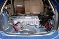
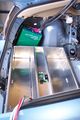
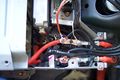
| − | ===OEM HV Battery Modifications===
| |
| − | {{Disclaimer}}
| |
| − | A number of wires are added within the OEM HV Battery box, including two HV cables which will exit the box and a short HV jumper cable through the HAL sensor. In addition one or more low voltage wires and taps may be added.
| |
| − | | |
| − | # Remove trunk carpet, all storage compartments, and spare tire.
| |
| − | # '''! ! Be Sure To Remove Orange HV Service Plug ! !'''
| |
| − | # Install HV taps to OEM NiMH battery Pack
| |
| − | ## Remove rear seat bottom, pull up front edge, unhook rear edge
| |
| − | ## Remove rear battery deck upholstery ''2x tie down clips ?10mm?, 2x tabs''
| |
| − | ## Remove drivers side rear seat back ''2x 14mm''
| |
| − | ## Remove drivers side rear seat pillow upholstery ''12mm, pull up''
| |
| − | ## Remove drivers side trunk panel upholstery ''10mm, 10mm screw, tabs''
| |
| − | ## Remove drivers side OEM Battery brace ''7x 12mm''
| |
| − | ## Remove OEM Battery ECU Cover ''2x 10mm, 2x 10mm nuts''
| |
| − | ### ''Optional steps'' <font color=red>'''Caution:''' This will expose you to the OEM HV Modules
| |
| − | ### Remove OEM Battery Input Air Duct ''2x tape, 1 sensor''
| |
| − | ### Remove Passenger side OEM Battery brace ''7x 12mm''
| |
| − | ### Remove '''OEM Battery Lid''' ''4x 12mm, 4x 10mm, 4x 10mm nuts, 1 tab at end''</font>
| |
| − | ## Add New HV Cables, Notch Here, Trim There, etc, etc
| |
| − | ## Reassemble in reverse order
| |
| − | # '' Replace Orange HV Service Plug ''
| |
| − | | |
| − | See Also:
| |
| − | *[http://www.airlabcorp.com/Prius/priusdisman.pdf PriusDisMan.pdf] <ref>[[Media:Priusdisman.pdf]] from http://www.airlabcorp.com/Prius/priusdisman.pdf</ref>
| |
| − | | |
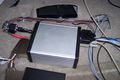
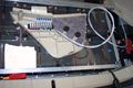
| − | ===Mount PFC Charger===
| |
| − | Install PFC Charger in the drivers side rear wheel well.
| |
| − | | |
| − | # Locate and drill mount points from pattern
| |
| − | # Install ventilation housing and fans
| |
| − | # Mount PFC Charger
| |
| − | | |
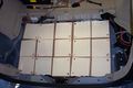
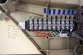
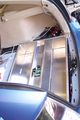
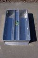
| − | ===Install Battery Box===
| |
| − | {{Disclaimer}}
| |
| − | | |
| − | Install the Battery Box.
| |
| − | # Locate, drill, and ''press nut'' body/frame mountpoints
| |
| − | # Attach ''Electronics Box'' to bottom of lower battery box frame
| |
| − | # Install and fasten lower battery box frame
| |
| − | # Populate box with batteries
| |
| − | # Install battery regulators and interconnects
| |
| − | # Install and fasten upper battery box frame
| |
| − | | |
| − | ===Connect Relay Box===
| |
| − | # Connect everything...
| |
| − | | |
| − | ===Drive and Enjoy===
| |
| − | '''Charge, Drive, and ''Repeat...'''''
| |
| − | | |
| − | ===References===
| |
| | <references/> | | <references/> |
| | | | |