|
General Disclaimer: (HV) (DC) injury or death hazard, use at your own risk, may void warranty. |
Escape PHEV TechInfo
Technical information on the Ford Escape useful when designing a Escape PHEV conversion.
2006 Year model
2007 Year model
Traction battery
Removal


From the hatch opening:
- Remove the carpet in the hatch compartment floor, to reveal the battery
- Turn the orange safety plug from LOCK to UNLOCK and pull it out
- Remove the black plastic air coupling on the rear-left
- Remove the bolts on either side of the battery (3 bolts on each side)
- Disconnect the battery:
- Orange HV connector on the right (flip the lever)
- Big black signal connector on the left (unscrews)
- Small connector next to the signal connector (snaps)
- Hook an engine hoist to the two round holes in the black metal on either side of the battery
- Hoist the battery out of the car
To open the battery:
- You need a #35 security Torx driver, and a #35 Torx driver
- Remove all the screws in the 2 top covers
- Cover over the fans
- Cover over the batteries and electronics
General description
Component locations
The battery includes (as seen when in the vehicle):
- Air blowers in the rear compartment
- NiMH cells in the center
- 2 layers of cells
- each layer in a left and right group
- each group has 13 columns of 5 cells in series
- total: 2 * 2 * 13 * 5 = 260 cells
- pack voltage: 1.3 V * 260 = 338 V
- controller on the right side
- contactors and HV connector on the right-front corner
- safety plug on the left-right corner
- a converter of some sort on the left side
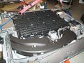
Battery pack opened, rear view
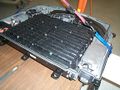
Battery pack opened, front view
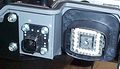
Battery pack data connector
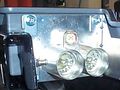
Battery pack power connector


Connectors
The battery has 3 connectors, with a total of 34 wires:
- C4227A - 28 wires - control
- C4227B - 2 wires - low power HV to the AC/DC converter
- C4227C - 4 wires - traction HV, interlock signals
Wire functions
Big control connector: C4227A
| Group | Ckt | Pin(s) | Name | Function | Notes |
| 12V pwr | 57 | 35,36,37 | Ground | Power ground | |
| 570 | 30,31 | Ground | Low power ground | ||
| 3800 | 4,5,6 | +12 V | Power +12V | Always on | |
| 16 | 10,11 | +12 V | Low power +12V | Always on | |
| 3206 | 19 | Voltage supplied in Start and Run | Receives 12 V when the car is on | From the ignition switch. Overload protected | |
| 3997 | 14 | Power sustain relay out | Receives 12 V when the Powertrain Control Module's Power Relay is on | The relay is located in the Battery Junction Box. The Powertrain Control Module is located under the hood, in the rear-center | |
| Air intake | 3703 | 21 | Battery compartment thermistor signal | Senses air intake temperature | All are located inside the column at the rear-left corner of car, inside air intake ducts |
| 3704 | 25 | Battery compartment thermistor return | |||
| 698 | 34 | Mode door actuator motor + | Moves a flap controlling air flow | ||
| 699 | 26 | Mode door actuator motor - | |||
| 1129 | 17 | Mode door actuator potentiometer + | Senses position of flap | ||
| 1130 | 20 | Mode door actuator potentiometer wiper | |||
| 1128 | 24 | Mode door actuator potentiometer - | |||
| 698 | 34 | Zone Valve | Solenoid selecting air source | ||
| CAN BUS | 1908 | 29 | High speed CAN bus + | Communicates with vehicle | See CAN section below for messages |
| 1909 | 28 | High speed CAN bus - | |||
| Jump start switch | 176 | 16 | Jump start switch feed | When grounded, lets 12 V battery be jump started from traction battery | The switch is located to the left of the driver's left ankle, behind a black plastic panel |
| 179 | 12 | Jump start switch illumination + | When at 12 V, it lights-up the switch
| ||
| Emergency control | 3003 | 8 | Battery power off signal | ??? | The Power Train Control Module is located under the hood, in the rear-center |
| 877 | 7,23 | Fuel pump feed / Inertia Sw input | Normally at +12V; open in case a crash opens an inertia switch | The High Voltage Cutoff switch is located in the right-rear column of the car | |
| 212 | 27 | Immediate shutdown 1 | The Transaxle Control Module tells the battery to remove power to the vehicle? | The Transaxle Control Module is under the hood, in the center, to the left of the box labeled "HYBRID" | |
| 213 | 13 | Immediate shutdown 2 |
CAN bus messages
- Kvaser has a simple explanation of the CAN bus.
- wikipedia article on the CAN bus
| General Disclaimer: (HV) (DC) injury or death hazard, use at your own risk, may void warranty. |
|---|
|
HV (High Voltage) DC (Direct Current) Warning: Traction Battery Packs, Motors, Chargers, and other HV sources could cause serious injury or death if proper precautions are not taken while working on or around such High Voltage Direct Current sources. Use this information at your own risk: There is no warranty expressed nor implied and we are not liable for any of your past, present, nor future actions. Even should you perform these modifications to the letter you could still damage any number of components in your vehicle causing it to no longer function. Even if it appears to function properly your actions may cause it to self destruct with collateral damage to surrounding properties other than your vehicle. By utilizing these ideas and instructions in an attempting to enhance national security, reduce gas consumption, vehicle "emissions", your carbon footprint, or smog, you do so at your own risk & peril. Warranty: In performing some of these modifications you may void your warranty with the vehicles manufacturer. See also our My wiki:General disclaimer |