|
General Disclaimer: (HV) (DC) injury or death hazard, use at your own risk, may void warranty. |
Difference between revisions of "PriusPlus-Instructions"
(spelling) |
(Added the battery box support instructions) |
||
| Line 95: | Line 95: | ||
Image:4 Finished Trays.JPG|All 4 finished trays laid out like they will be | Image:4 Finished Trays.JPG|All 4 finished trays laid out like they will be | ||
</gallery> | </gallery> | ||
| + | |||
| + | ==Battery Box Supports (Classic Method)== | ||
| + | Approx. Time Requirement: | ||
| + | |||
| + | ===Overview=== | ||
| + | The battery box supports are what the battery trays will sit on. In the classic method, aluminum angle irons are bolted onto 2 steel tubes which are bolted to the trunk. If you have choosen the alternative method, skip this section and goto the next section. | ||
| + | |||
| + | ===Tools Needed=== | ||
| + | * Chopsaw with metal cutoff blade (hacksaw or jig saw will also work) | ||
| + | |||
| + | ===Parts Needed=== | ||
| + | * 1 1/2 inch by 1/8 inch thick aluminum angle iron (2x 8 foot sections) | ||
| + | * 1 1/2 inch by 1/8 inch thick aluminum strip (1x 4 foot section) (optional for extra strength) | ||
| + | * 2 3 foot long 1/2 inch or 3/4 inch steel tubes. | ||
| + | * Screws, Nuts, Lockwashers, Bolts | ||
| + | |||
| + | ===Assembly Steps=== | ||
| + | # Cut 4 aluminum angle irons 38 inches long and layout so that 2 trays sit into each pair (see photos) ('''Todo''': Length may be slightly long, you will probably need to adjust the length when mounting!) | ||
| + | # Optionally cut the aluminum strip to the same length as the angle irons and set vertically in the middle of the assembly. This strip would then be bolted horizontally with the 2 center angle irons in the center and on each side. The idea is to reduce bounce in the center (weakest part) of the battery pack when going over bumps. | ||
| + | # Cut the steel tubes to the appropriate length ('''Todo''' Get exact length) | ||
| + | # Lay everything out as shown in the first photo and use the battery trays to determine the spacing. Leave enough space between the trays for a 1/4" nut. | ||
| + | # Mark the locations where the aluminum angles sit on the steel tube and drill holes. | ||
| + | # Drill holes in the opposite side of the steel tube, big enough to fit the head of a bolt through | ||
| + | # Drill 2 additional holes in each steel tube in the middle of where each tray will sit. Again, drill out the other side so a nut can be fit through it. Then put a threaded 5/8" threaded rod through the hole and put a nut on each side (and a lockwasher on one side.) This will serve as the holddown for the battery box top. | ||
| + | # Drill 4 holes through the tube, evenly spaced over the entire length. These holes are for mounting the battery box frame to the car. | ||
| + | # Drill additional holes as needed to support the electronics tray | ||
| + | # Once holes are all drilled, coat the steel tube with anti-rust paint / spraypaint. | ||
| + | |||
| + | ===Photos=== | ||
| + | <gallery> | ||
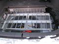
| + | Image:P1240040.JPG|The completed battery box sitting on steel tubes (unattached) | ||
| + | Image:Batt_Box_with_Bolt_Down_Angle.JPG|Shows how the box sits on the aluminum angle supports. Also includes optional 1 1/2 inch aluminum strip in center. | ||
| + | Image:Top_Battery_Box_With_Corner_Bracket.JPG|During construction, shows supports without optional strip in center. | ||
| + | </gallery> | ||
| + | |||
| + | ==Battery Box Supports (Alternative Method)== | ||
| + | [[Image:Alt Mounting Diagram.png|thumb|The alternative mounting method diagram]] | ||
| + | Approx. Time Requirement: 4-7 hours | ||
| + | |||
| + | ===Overview=== | ||
| + | In the alternative mounting method, the battery trays sit on aluminum angle irons which either sit directly on the trunk or on rubber pads (which allow the use of battery heaters.) The battery box is supported by brackets attached to the OEM battery mouting screws and two steel angle irons bolted to the trunk. If you have choosen the classic mounting method, skip this section. | ||
| + | |||
| + | ===Tools Needed=== | ||
| + | * Chopsaw with metal cutoff blade (hacksaw or jig saw will also work) | ||
| + | * Bench grinder | ||
| + | |||
| + | ===Parts Needed=== | ||
| + | * 1 1/2 inch by 1/8 inch thick aluminum angle iron (2x 8 foot sections) | ||
| + | * 1 1/2 inch by 1/8 inch thick aluminum strip (1x 4 foot section) (optional for extra strength) | ||
| + | * 16 inches of steel 1 1/2 inch angle iron | ||
| + | * 2 joist hangers for electrical conduit | ||
| + | * Screws, Nuts, Lockwashers, Bolts | ||
| + | * 1/4" nuts | ||
| + | * 1/4" or 1/8" rubber pads (optional, but required if heating pads are to be installed.) | ||
| + | * anti-rust paint or spraypaint | ||
| + | |||
| + | ===Assembly Steps=== | ||
| + | ===The center strip=== | ||
| + | # See the diagram to the right to see how everything assembles. | ||
| + | # Cut 4 aluminum angle irons 38 inches long and layout so that 2 trays sit into each pair (see photos) ('''Todo''': Length is too long, you will need to adjust the length when mounting, so be careful drilling holes, test fit first!) | ||
| + | # Optionally cut the aluminum strip to the same length as the angle irons and set vertically in the middle of the assembly (for strength). This strip would then be bolted horizontally with the 2 center angle irons in the center and on each side. The idea is to reduce bounce in the center (weakest part) of the battery pack when going over bumps. | ||
| + | # Lay out 2 aluminum angles so they form a "T" with the top of the "T" being on the floor. Optionaly insert the aluminum strip into the middle | ||
| + | # Lay everything out as shown in the first photo and use the battery trays to determine the spacing. Leave enough space between the trays in the middle for a 1/4" nut. | ||
| + | # Drill holes through each end of the assembly to anchor the two angles (and optionally the strip) together. The holes must be outside where the battery trays will sit (remember to leave space for a 1/4" nut (which is larger than 1/4") | ||
| + | # Optionally, cut rubber pads to go under each of the aluminum angles. | ||
| + | # Other holes will need to be drilled later when ready to mount. | ||
| + | |||
| + | ===Steel Angle Iron Brackets=== | ||
| + | # Cut 4 sections of steel angle iron about 1 to 1 1/2 inches long | ||
| + | # Drill a 3/8" hole in the center on one side of the angle iron. | ||
| + | # On the inside of the angle iron, weld (or use JB weld or another strong epoxy) a 5/8" nut on the inside so a bolt can go through the angle iron and into the nut | ||
| + | # Drill a 5/8" hole in the center of the other side of the angle iron | ||
| + | # Paint the steel with a clean metal anti-rust primer (then allow to dry) | ||
| + | # Spray or paint the primed steel with anti-rust paint | ||
| + | |||
| + | ===Steel Supports=== | ||
| + | # Cut 2 sections of steel angle iron about 4 inches long each | ||
| + | # Drill 2 5/8" holes in the bottom of the angle iron | ||
| + | # These will be used later for mounting into the Prius - the rest of the assembly must be done later | ||
| + | |||
| + | '''Todo''' This isn't finished - check the diagram for more details | ||
| + | |||
| + | |||
| + | ===Photos=== | ||
| + | <gallery> | ||
| + | Image:Batt_Box_with_Bolt_Down_Angle.JPG|Shows how the box sits on the aluminum angle supports. Also includes optional 1 1/2 inch aluminum strip in center. | ||
| + | Image:Alt method support angle irons.jpg|Test fitting in the Prius | ||
| + | Image:Welded_angle_iron_2.jpg|Support Steel mounted | ||
| + | Image:Rubber on center batt box support.jpg|Shows the optional rubber pads | ||
| + | Image:Right_side_battery_box_supports_alt_method.jpg|Detailed photo of the right side | ||
| + | Image:Left_side_battery_box_supports_alt_method.jpg|Detailed photo of the left side | ||
| + | Image:Entire_alt_batt_box_mounting_supports.jpg|With the battery trays in | ||
| + | </gallery> | ||
| + | |||
| + | |||
{{Disclaimer}} | {{Disclaimer}} | ||
Revision as of 02:10, 10 June 2007
| Click show for a short list of the current PHEV conversion and kit options for the Toyota Prius. |
|---|
|
For Prius conversion details see the Prius PHEV article and comparisons table.
|
|
--={ Project Overview
}={ 2007 Maker Faire
}={ Theory
}={ Instructions
}={ Parts List
}={ RawData
}={ Latest News
}=--
|
|---|
|
--={ Historic }={ Battery }={ Schematics }={ PseudoCode }={ Photos }=-- |
 Team Photo from the PriusPlus conversion of Sven's Prius from Nov 2006. This is the home of the PRIUS+ PHEV DIY (Do-it-Yourself) documentation. These pages are currently anonymously editable, which may change in the future. Please feel free to use the Discussion page for general discussion and commentary on the main article. If you would like to add to an existing section use the "edit" link near that topic's heading. Don't forget to use the Summary field to describe your changes. While editing use the "Show Preview" button to make sure your changes look like you expect them to, before you click "Save Page". |
Welcome to the PriusPlus Do-It-Yourself documentation. Below you will find details on converting your 2004-2007 Prius to a plug-in hybrid via the PriusPlus method. The documentation is laid out in three parts. The PriusPlus gives an overview of the conversion and lists benefits, limitations and normal operating behavior. PriusPlus-Theory gives details the theory behind how the conversion works. The PriusPlus-Instructions page (this page) gives detailed, ordered instructions on how to convert your Prius yourself.
Choosing a Mouting Method
Before getting too far, you will need to decide on a mounting method. Currently, there are 2 methods, each with their benefits. The majority of the instructions are the same for both methods, however, some sections will be labeled as "classic mounting method" and others as "alternative mounting method" and contain instructions for the specific method.
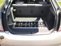
Classic Mounting Method
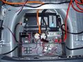
The "Classic" method is the classic CalCars style. The spare tire well is largely unchanged, the batteries are placed in the very rear of the trunk, an electronics tray is placed in front of the batteries and the charger is placed in the left cubby hole. This method allows for easy access to all the electronics, including the charger.
Classic method - spare tire well
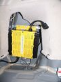
Classic method - charger


Alternative Mounting Method
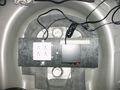
The "Alternative" method seeks to maximize usable trunk space and minimize visible changes. With this design, the batteries are moved as far forward as possible and the supporting electronics and charger are located in the spare tire well. The batteries stick up through the false floor, but are flush with the Prius's floor. Most of the high voltage electronics are isolated from the low voltage electronics, however some of the high voltage electronics and the charger are more difficult to access because they are below the batteries (they tend to be the more reliable parts, however.) The low voltage electronics are easily accessible.
Spare tire well
Location of Batteries
Finished Product


CAN-View & EV Mode button
Overview
Start by installing CAN-View. CAN-View gives you insight into how the Prius works and it is best to have it installed before doing the conversion. Please see PriusPlus-Theory for more information on what CAN-View and Prius EV Mode Button do and how they work.
You will need to purchase CAN-View from hybridinterfaces.ca. There are currently 4 versions of CAN-View available. Version 3 and 3plus require an '04 or '05 Prius and makes use of the built in display (or MFD) while Version 4 and 4plus work with an 04-07 Prius but requires an external touchscreen (since the built in touchscreens were changed in the '06 model and are no longer compatible.) Version 4 has the PHEV relays built onto the main board, while version 3 has an extra optional PHEV relay board, which is required for this conversion. Version 3plus and 4plus feature a smart relay board which can interact with battery regulators. At the present, the PriusPlus conversion method does not make use of the smart relay features in the "plus" models.
Installation
Approx. time requirement: 45 minutes - 2 hours
The CAN-View is installed differently depending on whether or not your car is equipped with in-dash navigation. Detailed instructions with photos are available with NAV or without NAV. It is best to install and route the wires for the Prius EV Mode Button at the same time since they both require disassembling the dash.
ToDo the following section is shared with the PiPrius_conversion_process#CAN-View_.26_EV_Mode_Button documentation. Any changes should be generic enough to satisfy both, place project specific notes above or below it. Another set of instructions may be needed for the CAN-View Version 4 which does not integrate with the OEM MFD and gets power directly from the OBDII port, Prius CAN View V4 Mounting options at PriusChat.com covers various ways of mounting the second touch screen.
Installing the CAN-View Version 3 and Prius EV Mode Button both involve disassembling the same areas of the Prius so will be covered here at the same time. You should also be familiar with these cv#reference materials.
- cv1. File:Stereo Accessory Install Guide 04 Prius v1.03.pdf from http://www.chrisdragon.com
- cv2. File:PriusXMradio3.2.pdf from https://www.metrotpn.com
- cv3. File:CAN-View installNONAVwt.pdf Adapted from http://www.hybridinterfaces.ca/installNONAV.html
- cv4. File:CAN-View installWNAVwt.pdf Adapted from http://www.hybridinterfaces.ca/installWNAV.html
- cv5. File:Prius-evbutton-install.pdf from http://www.calcars.org/prius-evbutton-install.pdf
- cv6. File:FactoryEV.pdf from http://www.scubadivervideo.com/Files/factoryEV.pdf
We begin by disassembling the dashboard. cv1 cv2
- Remove the bottom cover of steering column
- Releasing the steering wheel adjustment handle and removing the silver screw.
- Turn steering wheel 90 degrees to right and left to remove black screws on each side.
- Remove the lower cover by carefully pulling down on lower half.
- Disconnect the headlamp flasher plug on left side of steering column.
- Remove plugs cover by unlocking two side tabs/clips.
- Remove 3 unused connector pins using a jeweler's screwdriver to disengage and slide them out.
- Optionally to use the headlamp flasher circuit as an EV Mode button:
- Solder some length?? of black wire to a new pin and use it to replace:
The Red(#11-B10) wire to preserve day time flashing function, will disable night time flashing.It has been discovered that this does not work properly as the red wire is used for both the high beam and flash functions when the lights are turned on, thus disabling high beams at night. Anyone who has implemented this option should reinstall the red wire, moving the ev-mode button wire to the violet wires location instead.- The Violet(#17-B4) wire to preserve night time flashing function, will disable day time flashing.
- Route new black wire along existing bundle then towards center console to later meet up with OBDII cable.
- Snap the cover back onto the flasher plug and reinsert into switch.
- Reassemble steering column, be sure everything is aligned properly.
- Remove lower glove box by squeezing the inside sides together to lower box below catches, then unclip the small piston from right side. Lower box until the lower joints detach from dash, remove pneumatic cylinder noting it's orientation.
- Remove passenger side silver air vent cover by pulling out from the bottom first. Next remove the small interior colored piece just below the vent piece by pulling straight out.
- If installing CAN-View Without Navigation: cv3
- Remove drivers side air vent cover, press down and pull out on top.
- Remove lower center console hump with 12v lighter power socket, remove barb from passenger side, pull out.
- Remove air vent at right side of MFD screen, open upper glove box to pull out vent.
- Remove lower drivers side interior colored dash panel, one black screw above hood release, one exposed behind drivers side vent.
- Remove black lower dash key fob panel, leave hanging with wires connected.
- Remove upper drivers side dash panel with power button, leave wires attached.
- Remove air vent at left side of MFD screen, the shift lever with remain in place, detach and slide park button forward through silver panel to expose and detach cable, then remove the panel and reattach the park button to it's cable to prevent errors during later tests.
- Remove 10mm bolts, one on each side of MFD screen, pull screen out sharply and rotate towards drivers side.
- Tap grey OEM wire for 12v power, top row 2nd from the left.
- Attach CAN-View video cable to MFD and power spade to tapped grey wire, run cable out directly behind screen.
- Connect CAN-View OBDII cable to OBDII port and route cable behind center console towards glove box along with headlamp flasher ev-mode button wire if installed.
- Test CAN-View, then reassemble center and drivers side of dash.
- CAN-View will be mounted under passenger seat, above JBL amplifier if present.
- If installing CAN-View With Navigation: cv4
- Route OBDII Cable around foot well and down drivers side door sill to underneath drivers seat. Route headlamp flasher ev-mode button wire if installed behind center console and glove box.
- Tap grey OEM wire from navigation unit for 12v power.
- Connect CAN-View video cables to navigation unit.
- Test and attach above and to rear of navigation unit.
- Solder new pin to some length?? of black wire, and optionally the black wire which connects to the headlamp flasher.
- Install pin with black wire(s) to ev-mode button location in HV ECU H14#27. cv5 cv6
- The HV ECU is the one closest the exterior of the car with grey plugs.
- H14 is the lowest of the four connectors.
- Pin #27 is located on the most interior (broken into three segments) row, the second from the bottom left corner, in the only open location between two red wires.
- Using a jeweler's screwdriver raise the white terminal retainer, fully insert the new pin, re-compress the retainer, and plug terminal back into HV ECU.
- Route black EV Mode wire, and OBDII & Video if non-NAV, along passenger side door trim exiting under carpet before pillar to the hole in carpet below passenger seat and to relay cable.
- Route relay cable from CAN-View under rear passenger side door trim towards rear of car.
- Reassemble passenger side of dash and door trim.
Finally, Connect all the cables to CAN-View.
Battery Tray Construction
Overview
The next step is to start constructing the mechanical components which will be used in the conversion. The battery trays are where the new lead-acid (PbA) batteries will sit. The trays will then be mounted on rails in the trunk and a top will be placed over it to secure the batteries down. The battery trays are the same for both the classic and alternative mounting methods.
Approx. Time Requirement: 10-12 hours
Tools needed
- Metal Drill Bits: 3/32, 1/8, 5/32, 7/32
- Hacksaw with metal blade (or other method of cutting 1/8 inch aluminum)
- Drill or Dremel
- Drill or Dremel press recommended
- Metal file for filing rough edges.
- Wood saw
- Pop riveting tool
- Grinder (either an attachment for Dremel or bench grinder)
Parts needed
- Aluminum material
- Either 3/4" or 1" by 1/8" thick aluminum angle iron (2x 8 foot sections, 1x 4 foot section)
- 1/4" Aluminum channel iron (1x 8 foot section, 1x 4 foot section)
- 32 5/32 thick, 1/4 inch grip pop rivets
- 32 #4 flat head self threading screws at least 1/2 inch long
- Small piece of plywood for making jig (optional, but makes things easier.)
- Small pieces of wood for making jig (optional)
- Wood screws (optional)
Assembly Steps
- Cut 4 sections of the 1/4" aluminum channel iron to the exact length of the batteries (should be 7 1/16 inches.) Having the batteries actually present is important for measuring. A total of 16 of these pieces will be required for all 4 trays.
- Lay out 5 batteries and put the 1/4" aluminum channel irons between the batteries. Measure out the length and cut 2 sections of the aluminum angle irons to the length of the batteries (should be 16 5/16 inches.) A total of 8 of these sections will be required for all 4 trays. See photos below for how to layout the pack.
- Layout 5 batteries with the angle irons from above and measure the width and cut the 2 end pieces (should be 7 1/4 inches.) A total of 8 of these pieces will be required for all 4.
- Lay everything out on top of a piece of plywood and double check measurements with batteries set in the tray as shown below. It is important that the end pieces are under the pieces that run along the length of the tray.
- Screw down blocks of wood around outside of the frame as shown to hold the outside angle irons exactly where they are.
- Remove the batteries one by one and put in pieces of wood where the batteries were to hold frame and aluminum channel irons in place. This jig will hold all the pieces together while drilling.
- Using a small drill press or preferably a Dremel drill press, drill 2 3/32" holes into each corner (or probably only one if using 3/4" angle irons.)
- Once the holes are drilled, remove the top angle iron (the 16 5/16 inch one) and using a 1/8" drill bit, widen the holes so that the #4 screws can pass through them freely (only do this on the longer angle iron, not the bottom!) Then counter-sink with a 7/32" drill bit so that the screw will sit flush in the aluminum (see photo below.)
- Put in #4 self threading screws. The screws should grab into the smaller angle iron and hold the angle irons together firmly. The screws will stick out the other side.
- Using a cutoff attachment on a Dremel (or a hacksaw, but Dremel works much better), cut the screws off. Then grind them down flat using the cut off attachment on a Dremel or a bench grinder.
- Re-insert the finished angle iron frame into jig, and place channel irons in place. Drill 5/32" holes at each end.
- Using a pop-riveting tool, insert 5/32" aluminum rivets into the channel irons from the bottom and tighten.
- Repeat 3 more times for a total of 4 trays.
Photos
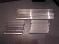
All necessary cut aluminum pieces for 4 trays
Tray set together with batteries
Tray parts laid out
Place wood around tray frame
Inserting wood blocks to hold aluminum
Inserting wood blocks to hold aluminum
Holes drilled in aluminum
Finished corner with screws in
Shows the self threading screws sticking out
The finished tray
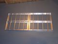
All 4 finished trays laid out like they will be


Battery Box Supports (Classic Method)
Approx. Time Requirement:
Overview
The battery box supports are what the battery trays will sit on. In the classic method, aluminum angle irons are bolted onto 2 steel tubes which are bolted to the trunk. If you have choosen the alternative method, skip this section and goto the next section.
Tools Needed
- Chopsaw with metal cutoff blade (hacksaw or jig saw will also work)
Parts Needed
- 1 1/2 inch by 1/8 inch thick aluminum angle iron (2x 8 foot sections)
- 1 1/2 inch by 1/8 inch thick aluminum strip (1x 4 foot section) (optional for extra strength)
- 2 3 foot long 1/2 inch or 3/4 inch steel tubes.
- Screws, Nuts, Lockwashers, Bolts
Assembly Steps
- Cut 4 aluminum angle irons 38 inches long and layout so that 2 trays sit into each pair (see photos) (Todo: Length may be slightly long, you will probably need to adjust the length when mounting!)
- Optionally cut the aluminum strip to the same length as the angle irons and set vertically in the middle of the assembly. This strip would then be bolted horizontally with the 2 center angle irons in the center and on each side. The idea is to reduce bounce in the center (weakest part) of the battery pack when going over bumps.
- Cut the steel tubes to the appropriate length (Todo Get exact length)
- Lay everything out as shown in the first photo and use the battery trays to determine the spacing. Leave enough space between the trays for a 1/4" nut.
- Mark the locations where the aluminum angles sit on the steel tube and drill holes.
- Drill holes in the opposite side of the steel tube, big enough to fit the head of a bolt through
- Drill 2 additional holes in each steel tube in the middle of where each tray will sit. Again, drill out the other side so a nut can be fit through it. Then put a threaded 5/8" threaded rod through the hole and put a nut on each side (and a lockwasher on one side.) This will serve as the holddown for the battery box top.
- Drill 4 holes through the tube, evenly spaced over the entire length. These holes are for mounting the battery box frame to the car.
- Drill additional holes as needed to support the electronics tray
- Once holes are all drilled, coat the steel tube with anti-rust paint / spraypaint.
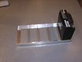
Photos
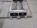
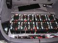
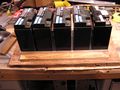
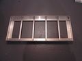
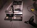
The completed battery box sitting on steel tubes (unattached)
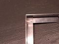
Shows how the box sits on the aluminum angle supports. Also includes optional 1 1/2 inch aluminum strip in center.
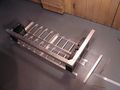
During construction, shows supports without optional strip in center.


Battery Box Supports (Alternative Method)

Approx. Time Requirement: 4-7 hours
Overview
In the alternative mounting method, the battery trays sit on aluminum angle irons which either sit directly on the trunk or on rubber pads (which allow the use of battery heaters.) The battery box is supported by brackets attached to the OEM battery mouting screws and two steel angle irons bolted to the trunk. If you have choosen the classic mounting method, skip this section.
Tools Needed
- Chopsaw with metal cutoff blade (hacksaw or jig saw will also work)
- Bench grinder
Parts Needed
- 1 1/2 inch by 1/8 inch thick aluminum angle iron (2x 8 foot sections)
- 1 1/2 inch by 1/8 inch thick aluminum strip (1x 4 foot section) (optional for extra strength)
- 16 inches of steel 1 1/2 inch angle iron
- 2 joist hangers for electrical conduit
- Screws, Nuts, Lockwashers, Bolts
- 1/4" nuts
- 1/4" or 1/8" rubber pads (optional, but required if heating pads are to be installed.)
- anti-rust paint or spraypaint
Assembly Steps
The center strip
- See the diagram to the right to see how everything assembles.
- Cut 4 aluminum angle irons 38 inches long and layout so that 2 trays sit into each pair (see photos) (Todo: Length is too long, you will need to adjust the length when mounting, so be careful drilling holes, test fit first!)
- Optionally cut the aluminum strip to the same length as the angle irons and set vertically in the middle of the assembly (for strength). This strip would then be bolted horizontally with the 2 center angle irons in the center and on each side. The idea is to reduce bounce in the center (weakest part) of the battery pack when going over bumps.
- Lay out 2 aluminum angles so they form a "T" with the top of the "T" being on the floor. Optionaly insert the aluminum strip into the middle
- Lay everything out as shown in the first photo and use the battery trays to determine the spacing. Leave enough space between the trays in the middle for a 1/4" nut.
- Drill holes through each end of the assembly to anchor the two angles (and optionally the strip) together. The holes must be outside where the battery trays will sit (remember to leave space for a 1/4" nut (which is larger than 1/4")
- Optionally, cut rubber pads to go under each of the aluminum angles.
- Other holes will need to be drilled later when ready to mount.
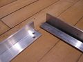
Steel Angle Iron Brackets
- Cut 4 sections of steel angle iron about 1 to 1 1/2 inches long
- Drill a 3/8" hole in the center on one side of the angle iron.
- On the inside of the angle iron, weld (or use JB weld or another strong epoxy) a 5/8" nut on the inside so a bolt can go through the angle iron and into the nut
- Drill a 5/8" hole in the center of the other side of the angle iron
- Paint the steel with a clean metal anti-rust primer (then allow to dry)
- Spray or paint the primed steel with anti-rust paint
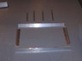
Steel Supports
- Cut 2 sections of steel angle iron about 4 inches long each
- Drill 2 5/8" holes in the bottom of the angle iron
- These will be used later for mounting into the Prius - the rest of the assembly must be done later
Todo This isn't finished - check the diagram for more details
Photos
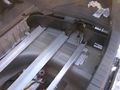
Shows how the box sits on the aluminum angle supports. Also includes optional 1 1/2 inch aluminum strip in center.
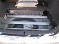
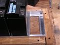
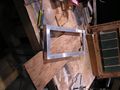
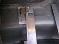
Test fitting in the Prius
Support Steel mounted
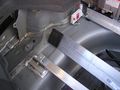
Shows the optional rubber pads
Detailed photo of the right side
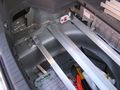
Detailed photo of the left side
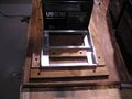
With the battery trays in


| General Disclaimer: (HV) (DC) injury or death hazard, use at your own risk, may void warranty. |
|---|
|
HV (High Voltage) DC (Direct Current) Warning: Traction Battery Packs, Motors, Chargers, and other HV sources could cause serious injury or death if proper precautions are not taken while working on or around such High Voltage Direct Current sources. Use this information at your own risk: There is no warranty expressed nor implied and we are not liable for any of your past, present, nor future actions. Even should you perform these modifications to the letter you could still damage any number of components in your vehicle causing it to no longer function. Even if it appears to function properly your actions may cause it to self destruct with collateral damage to surrounding properties other than your vehicle. By utilizing these ideas and instructions in an attempting to enhance national security, reduce gas consumption, vehicle "emissions", your carbon footprint, or smog, you do so at your own risk & peril. Warranty: In performing some of these modifications you may void your warranty with the vehicles manufacturer. See also our My wiki:General disclaimer |