|
General Disclaimer: (HV) (DC) injury or death hazard, use at your own risk, may void warranty. |
Escape PHEV TechInfo
Contents
- 1 Traction battery
- 2 Battery current
- 3 SOC
- 4 CAN bus messages
- 5 Test data display
- 6 Engine, Motors, RPM's, and Ratios
Technical information on the Ford Escape useful when designing a Escape PHEV conversion.
Unless otherwise noted, everything refers to a 2007 year model, belonging to Hybrids Plus.
Traction battery
Specs
- Cells:
- 250 Sanyo NiMH 'D' cells, divided into 50 modules of 5 cells each
- 325 V nominal @ 1.3V/cell (Ford says 330V)
- 5.5 Ah
- Electronics:
- controller
- DC-DC converter to charge traction battery from 12 V battery ("Jump Start")
- Contactors and pre-charge relay / resistor
- Current sensor
- Blowers
- Connectors:
- 12 V power and control (40 circuits)
- HV (4 circuits)
- AC/DC (2 circuits, unused)
- Mechanical
- 87 kg (192 lb)
- 102 x 80 x 15 cm (40 x 31-1/2 x 6")
Performance
Voltage vs SOC

When the car is parked, ignition on, the engine cycles off and on over time, to keep the battery within certain SOC levels. This plot of Battery Voltage vs Battery SOC shows that cycle.
- When the engine is on, it charges the battery at about 13 A, and the battery voltage jumps up (due to its internal resistance) and starts climbing.
- When the SOC reaches up to 51 %, the engine stops charging at high current
- The engine stays on a bit longer, to finish warming itself up, charging the battery at lower current (hence the battery voltage drops, though the SOC still increases)
- The engine turns off, and the battery voltage creeps down as the battery is slowly discharged by the car's loads (the headlights were on during this test)
- When the SOC reaches down to 41 %, the engine comes on and the cycle repeats

When the car is parked, key on / ignition off, the battery is discharged until 35 %, when the car starts using its 12 V battery instead. This plot of Battery Voltage vs Battery SOC shows that; it starts from a relatively high SOC (after coming down a mountain).
- To speed-up the test, the headlights are on, and then also the fan (drawing between 0.6 and 2 A, still considered "no load").
- The perturbation in the middle is because, after some time, the car switched to the 12 V battery, so the test had to be stopped, and then started again later
- The temperature is between 30 and 32 °C
- The voltage is approximately: 245 [V] + 1.75 [%/V] * SOC [%]
Internal resistance
From the delta in the voltage (27 V) charging (13 A) and a no current, we derive that the battery has a resistance of 2.1 ohm.
Assuming an average current of 50 A during operation, that's 5 KW of wasted heat! No wonder the battery needs air conditioning!
Removal
From the hatch opening:
- Remove the carpet in the hatch compartment floor, to reveal the battery
- Turn the orange safety plug from LOCK to UNLOCK and pull it out
- Remove the black plastic air coupling on the rear-left
- Remove the bolts on either side of the battery (3 bolts on each side)
- Lift the bottom of the rear-right passenger seat and move it forward
- List the strip of carpet to reveal the metal cover over the high voltage cables
- Remove the 2 (not 3) nuts holding the black metal cover
- Flip the seat forward to see the other end of the black metal cover
- Remove the 2 bolts holding the other end of the black metal cover to the battery
- Disconnect the battery:
- From the rear right seat, remove the orange HV connector on the right (flip the lever)
- From the rear left seat, remove the big black signal connector on the left (unbolts with a 10 mm socket wrench)
- From the rear left seat, remove the small connector next to the signal connector (snaps)
- Remove the battery
- Remove the 6 bolts, 3 on each side of the battery, bolting it to the floor (1/2" socket)
- Hook an engine hoist to the two round holes in the black metal on either side of the battery
- Hoist the battery out of the car
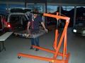
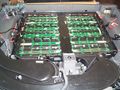
Battery pack lifted out of vehicle
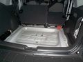
Trunk after the battery was removed


To open the battery:
- You need a #35 security Torx driver, and a #35 Torx driver
- Remove all the screws in the 2 top covers:
- Cover over the fans
- Cover over the batteries and electronics
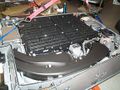
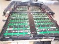
Battery pack opened, rear view
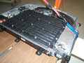
Battery pack opened, front view


Component locations

The battery includes (as seen when in the vehicle):
- Air blowers in the rear compartment
- NiMH cells in the center
- 2 layers of cells
- each layer in a left and right group
- the groups in the top layer have 13 columns of 5 cells in series
- the groups in the bottom layer have 12 columns of 5 cells in series
- total: 2 * 13 * 5 + 2 * 12 * 5 = 250 cells
- nominal pack voltage: 1.2 V * 250 = 300 V
- controller on the right side
- contactors and HV connector on the right-front corner
- HV safety plug on the right-rear corner. The current sensor is inside it
- the Converter on the left side
Cell array
These pictures show the two layers of cells, separated. The upper layer is removed and upside-down. Note the electronics potted in the middle of the layer. All indications are that these electronics provide insulation, and that therefore all the wires coming out of the cell pack (other than the high voltage wires) are at low voltage.
Lower cell array
Upper cell array
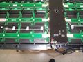
Cell array detail


Disconnect
The safety disconnect includes the current sensor: Microchip PowerSmart Systems PS3190-256 PowerShunt. This part is not available: it must be custom made for this battery. It is a combination resistive shunt, current sensor, A/D converter and digital communication.
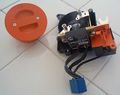
Safety disconnect socket and plug
Safety disconnect socket showing shunt


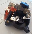
Contactors assembly
This assembly includes 2 high power contactors, a low current precharge relay, and a precharge resistor (dangling, in the picture)
Contactor assembly '05 to '08
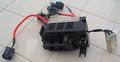
Contactor assembly '09, opened


Note the precharge resistor (white box) the 3 contactors (gray box) sense resistors (small black potted boxes at the end of thr orange wires
Block diagram

This block diagram shows the main components of the battery pack, and how they interface to the vehicle
- The NiMH cells store energy
- The battery controller controls the battery pack
- It communicates with the vehicle through the CAN bus
- It monitors the air intake temperature, it controls the intake air flow and source, and it drives to DC blowers to blow air into the cells
- It monitors the cells' voltage, including in intermediate points of the pack ("taps")
- ...
- The DC-DC converter receives power from the 12 V battery and boosts it up to 300 V, to charge the traction battery when it's dead and the user presses the Jump Start button (by the driver's left foot)
- The Safety Disconnects opens the pack mid-voltage
- The HV Output section
- It has a connector with 2 high-current contacts to connect the battery voltage to the vehicle
- It has a pair of wires to determine if that connector is connected or not
- It has contactors (high power relays) to connect or isolate the pack voltage
- The blower compartment has 2 DC blowers to blow air into the cells
Wiring diagram

This wiring diagram shows how the components of the battery pack are wired together.
- High voltage wires are red.
- Connectors are marked with their color and the number of positions
- Sets of wires are shown together. The slash at one end indicates the number of wires
- The function of sets of wires is shown above the wire
- The wire colors are shown below the set of wires
- Shaded squares indicate that wires are bundled together
- The orientation of the components is shown as seen when looking from the hatch
This reverse engineering drawing is not guaranteed to be accurate and is offered as-is. Please direct corrections to DavideAndrea.
Connectors

The battery has 3 connectors, with a total of 34 wires:
- C4227A - 40-circuits, 28 wires - control
- C4227B - 6-circuits, 2 wires - low power, 24v DC from the AC/DC converter
- C4227C - 4-circuits, 4 wires - traction HV, interlock signals
AC/DC converter connector: C4227B


Pin-out. Looking into cable (left) and looking into battery (right)
The AC/DC converter connector has 2 circuits, with the following names and functions.
| Group | Ckt | Pin(s) | Ext. color | Int. color | Name | Function | Notes | |
| AC/DC converter in | 3000 | 1 | Vio | Red | AC/DC in+ | To connect 24v DC to the traction battery, part of the engine block heater option | Ends in hood, by coolant tanks, unconnected and capped | OK |
| 3001 | 6 | VioOrg | Blk | AC/DC in- | OK |
This connector is on one end of a cable. The other end of the cable (C1468) is capped, under the hood, on the right, in front of the 2 coolant tanks, fastened to its own harness. It is only used with the Engine Block Heater option, which includes a small 115 Vac to 24 Vdc converter. Ford's part numbers for the block heater option are 4M6Z-6B018-AA WIRE ASY, F5RZ-6A051-B HEATER ASY, 5M6Z-10B689-AA CHARGER ASY. When the engine block heater is plugged into the 115 VAC, a "Y" splitter sends some power to the AC/DC converter, and then to the traction battery. It might only charge when the HV battery reaches a low SoC or it may simply be a battery warmer, because under normal battery conditions and room temperatures, zero power is sent to the traction battery pack. The engine block heater is rated at 115v AC and 400 watts. The AC/DC transformer outputs 24v DC under no load and when plugged into a cold battery draws 75 watts. Upon initial testing, a 7'C HV battery was warmed to 32'C in about 3 hours.
Control connector: C4227A


Pin-out. Looking into cable (left) and looking into battery (right)
- The control connector has 40 positions, but only 24 circuits
- To disconnect it, turn the bolt, which draws the connector out
- To remove the bulkhead male from the battery, remove the black shroud, squeeze the 2 gray snaps left and right, pull into the battery body
- To remove a pin form either mate, look on the mating surface, find the white, rectangular, plastic retainer, use a small flat screwdriver to lift the little snaps, lift the retainer. On the wire side, pull on the wire for that pin, while, on the pin side, use the small screwdriver to release the gray plastic snap holding the pin. Pull the wire and the thin out.
Names and functions.
| Group | Ckt | Pin(s) | Ext. color | Int. color | Name | Dir | Function | Notes | |
| 12V pwr | 57 | 35,36,37 | Blk | Blk | Ground | IN | Power ground | OK | |
| 570 | 30,31 | BlkWht | BlkWht | Ground | IN | Signal ground | OK | ||
| 3800 | 4,5,6 | LtgrnBlk | Red | +12 V | IN | Power +12V | Always on | OK | |
| 16 | 10,11 | RedLtgrn | RedBlu | +12 V | IN | Low power +12V | Always on | OK | |
| 3206 | 19 | LtgrnYel | TanRed | Voltage supplied in Start and Run | IN | Receives 12 V when the ignition switch is in either the On or Start positions (even if engine is not running) | From the ignition switch. Overload protected | OK | |
| 3997 | 14 | Dkgrn | Tan | Power sustain relay out | IN | Receives 12 V when the ignition switch is in either the On or Start positions (even if engine is not running) and for 2 seconds after the ignition is turned off | Fed by the Powertrain Control Module's Power Relay, located in the Battery Junction Box. The Powertrain Control Module is located under the hood, in the rear-center | OK | |
| Air intake | 3703 | 21 | BrnWht | BlkBrn | Battery compartment thermistor signal | IN | Senses air intake temperature | All are located inside the column at the rear-left corner of car, inside air intake ducts | n.a. |
| 3704 | 25 | DkgrnWht | WhtBlk | Battery compartment thermistor return | IN | n.a. | |||
| 698 | 34 | Red | RedBlu | Mode door actuator motor + | OUT | Moves a flap controlling air flow | n.a. | ||
| 699 | 26 | Org | BlkYel | Mode door actuator motor - | OUT | n.a. | |||
| 1129 | 17 | BrnWht | RedGRn | Mode door actuator potentiometer + | OUT | Senses position of flap | n.a. | ||
| 1130 | 20 | PnkLtgrn | BluBlk | Mode door actuator potentiometer wiper | IN | n.a. | |||
| 1128 | 24 | GryLtBlu | BlkWht | Mode door actuator potentiometer - | OUT | n.a. | |||
| 698 | 34 | Red | RedBlu | Zone Valve | OUT | Solenoid selecting air source | n.a. | ||
| CAN BUS | 1908 | 29 | Wht | YelRed | High speed CAN bus + | I/O | Communicates with vehicle | See CAN section below for messages | OK |
| 1909 | 28 | Blk | YelWht | High speed CAN bus - | I/O | OK | |||
| Jump start switch | 176 | 16 | PnkLtgrn | BrnWht | Jump start switch feed | IN | When grounded, lets 12 V battery jump charge-up the traction battery a bit, through DC-DC converter in battery pack, enough to start the car | The switch is located to the left of the driver's left ankle, behind a black plastic panel | OK |
| 179 | 12 | OrgRed | GrnBlk | Jump start switch illumination + | OUT | When at 12 V, it lights-up the switch | OK | ||
| Emergency control | 3003 | 8 | VioWht | Tan | Battery power off signal | OUT | 0-12 V square wave, 50% duty cycle. If all OK, 2 Hz. If problem, 6 Hz. From the Traction Battery to the Power Train Control Module | The Power Train Control Module is located under the hood, in the rear-center | OK |
| 877 | 7,23 | Wht | RedBlk | Fuel pump feed / Inertia Sw input | IN | Normally receives 12 V when the ignition switch is in either the On or Start positions (even if engine is not running) and for 2 seconds after the ignition is turned off; no voltage when the ignition is off, or in case a crash opens an inertia switch | The High Voltage Cutoff switch is located in the right-rear column of the car | OK | |
| 212 | 27 | Dkblu | BlkBlu | Immediate shutdown 1 | OUT | The Traction Battery tells the Transaxle Control Module that all is OK by sending 12 V (same duration as the Sustain line). If both lines are open, the Transaxle Control Module starts a fault | The Transaxle Control Module is under the hood, in the center, to the left of the box labeled "HYBRID" | OK | |
| 213 | 13 | DkbluYel | BlkRed | Immediate shutdown 2 | OUT | OK | |||
| Unused | n.a. | 18 | n.a. | TanRed | ??? | ??? | ??? | Connected to controller, not used in vehicle | ?? |
| 32 | YelBlk | ?? |
Notes
- Green OK: function is understood and confirmed
- Red ??: function is not understood, or not yet confirmed
- Gray n.a.: PHEV conversion can work without this function
Immediate Shutdown
With these two lines, the battery tells the Transaxle Control Module that all is OK.
- Whenever there's 12 V on the Start / Run, and all is OK, the battery sends 12 V to both Immediate Shutdown lines
- The load in the Transaxle Control Module on each line is 1.2 Kohm
- If *both* lines are open, the Transaxle Control Module shows a fault (if only one line, then all is OK)

HV connector: C4227C


Pin-out. Looking into cable (left) and looking into battery (right)
Part specs: Yazaki
- Male (on battery) P/N 7325-6498-02 or 7325-6499-02
- Female (on cable) P/N 7325-6490-51
- Spec sheet (pdf)
The HV connector has 4 circuits, with the following names and functions.
| Group | Ckt | Pin(s) | Ext. color | Int. color | Name | Function | Notes | |
| HV | 3180 | + | Org | n.a. | HV+ | Battery power | To Transaxle Control Module | OK |
| 3181 | - | Org | HV- | OK | ||||
| Interlock | 3130 | 1 | Gry | Blu | Traction Battery Control Module Interlock + | Detects if HV connector is mated. The battery and the Transaxle Control Module both look at the voltage at these pins. | To Transaxle Control Module | OK |
| 3181 | 2 | Red | Wht | Traction Battery Control Module Interlock - | OK |

The electrical circuit for the HV Interlock. The circuit goes from the battery, through the Transaxle Control Module, and back to the battery. If either wire is opened, shorted to +12 V or grounded, both the Battery and the Transaxle Control Module detect a fault.
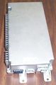
Electronic Components
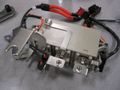
The controller
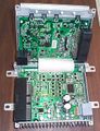
The controller, opened. The low voltage board is at the bottom, the high voltage one at the top
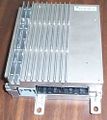
The Jump Start Converter


Battery cooling system


The Cooling System controls the temperature of the NiMH cells in the traction battery.
Its components are located:
- in the rear-left column
- in the traction battery itself
When used in a closed loop, air flows:
- from the empty spaces in the battery pack
- out of the rear-most grille in the rear-right corner of the battery pack
- into a duct in the rear-right column of the vehicle
- up the rear duct in that columns
- through the Mode Door that controls the air flow (unconfirmed)
- through the Zone Valve that selects the air source (unconfirmed)
- forward through a heat exchanger
- down the front duct
- out of the rear-right column
- into the front-most grille in the rear-right corner of the battery pack
- into the battery pack
- into 2 ducts, one for each blower
- into 2 blowers, one for each duct
- into each set of cells (left set for left blower, right for right)
- through the cells and into the empty spaces in the battery pack
- completing the cycle
The heat exchanger is chilled by the vehicle's air conditioning system. This is done through two metal pipes, which run from the bottom left corner of the vehicle, then forward, behind (to the left of the) black plastic ducts, and up to the heat exchanger. Condensation collected in the heat exchanger flows into two rubber tubes below it, through a Y into a single rubber tube, through the floor, to let the condensation drip on the ground.
When using outside air:
- air is taken from a vent in the rear-right window
- down a duct
- flows through an air filter
- through the Mode Door
- into the heat exchanger
- then following the same path as above
Now that extra air has been taken into the system, air has to be let out of it
- air from the pack flows into the rear duct
- the Zone Valve opens, letting out air from the rear duct into the open space in rear-right column
- from there, air flows into the rear storage area
To monitor the temperature, thermistors are placed:
- 1 in the rear-right ducts
- 2 by the blowers, one for each blower
- 2 in the left block of cells, 2 in the right block (unconfirmed)
To control the air flow and temperature:
- the blower's speed is variable
- the Mode Door's position is continuously variable from closed to fully open
- the Zone Valve selects the air source
The vehicle varies the blowers' speed based on the battery temperature. However, their speed is reduced when the vehicle is otherwise quiet (engine off, low speed or stopped), presumably to prevent them from annoying the passengers. Source
- 10 % when stopped
- from 10 % to 80 % as the car speed goes between stopped and 25 mph, with the engine on
- 80 % if in EV Mode or the car speed is between 25 and 39 mph
- 100 % if the speed is 40 mph or above

Contactors
The Traction Battery uses 3 contactors (high power relays) to connect the battery voltage to the HV output.
- The contactors are located just behind the HV output connector
- The enclosure includes 1 precharge resistor and filter capacitors

- The purpose of contactor K1 is to precharge the capacitors in the Motor Driver slowly
- Contactor K2 connects the B+ of the battery to the HV connector
- Contactor K3 connects the B- of the battery to the HV connector
- The circuit includes the interlock which detects if the HV connector is disconnected.

Sequence:
- The CAN Bus activity starts 25 ms after the ignition is turned on
- At 150 ms after the ignition is turned on, A CAN message (422h, byte 1 = 1Eh (models '05 through '08) or 2Eh (model '09)) tells the battery to turn on its relays
- Then the precharge and B- contactors (K1 and K3) are turned on, to precharge the Motor Driver capacitors. There's a spike in the current reflecting the inrush. The time constant is measured to be about 35 ms. Given that the precharge resistor is 10 ohm, we derive that the capacitors in the inverters are 3.5 mF (that's 3.5 milliFarad).
- At 416 ms, the B+ contactor is turned on (K2) to apply the full battery voltage to the Motor Driver. There's a small step in the current, as the precharge resistor is no longer in the circuit.
- At 496 ms, the B+ contactor is on, the precharge contactor is no longer needed, so it can be turned off.
- The battery puts on the CAN Bus a message (300h, byte 3) that the contactors are on and all is OK.
Notes:
- Initially, the contactors are powered by the full 12 V voltage. After a bit, since they are already actuated, their coil voltage can be halved without dropping off the contact, to reduce their heating.
- Initially, the supply voltage is 12 V. Later, the DC-DC converter that keeps the 12 V battery charged is turned on, so the 12 V supply jumps up to 14 V
Contactor control message
The vehcile controls the contactors through message 422h (50 ms, 2 bytes), data byte 1.
- Contactors off: 00h
- Contactors on: depends on year model.
For '05 to '08 models:
- Contactors on: 1Eh
For '09 models: Contactors on sequence:
- 1A: 0001 1001
- 2D: 0001 1101
- 2E: 0001 1110
Clearly, the vehicle controls each contactor directly:
- bit 0: K1 (precharge)
- bit 1: K2 (negative)
- bit 2: K3 (positive)
Battery compartment
SolidWorks 3-D model of cavity containing the battery (useful for designing replacement batteries).
Battery current
- The Main Fuse in the Battery is 100 A. Therefore, we assume that the battery current is at most +/- 100 A. If the assumptions of CCL (12) and DCL (13) are correct, the range is actually +/- 78 A.
Here are some numbers:
- Engine off, stopped: 1.2 A
- Engine off, stopped, low beam: 1.9 A
- Engine off, stopped, high beam: 2.7 A
- Stopped, charging, headlights off: - 3.6 A (normal SOC) or -14 A (low SOC)
When stopped, with the engine on, the charging current depends on the reported SOC.

If the engine has no other reason to stay on (such as the air conditioning being on, or the catalytic converter is cold), then the engine comes on when the SOC drops to 39 %, and turns off when the SOC goes above 42 %.
SOC
- SOC ranges at least from 35 % to 60 %
- When stopped, a SOC of 39 % makes the engine come on to start charging
- When stopped, a SOC of 42 % makes the engine go off to stop charging, unless the engine is on for some other reason
Below from gpsman1@yahoo.com
- When the key is in "RUN" (does not matter if the car has been "started" or not) the HV battery will provide power via DC/DC stepdown converter for all 12v accessories first, and for as long as it is able. Only when depleted to a certain level, will some relays open, and the power source will be handed over to the 12v under hood battery.
- The HV battery cuts off and allows the 12v battery to take over at a lower limit to protect itself from over discharge.
- The exact SOC is unknown, but believed to be in the 35% to 39% range.
- The HV battery will cut out, and hand 12v accessories ( lights, fans, radio ) to the 12v battery when the voltage drops below 305 volts and the car has not been started with the key ( just in run ) or the car cannot automatically re-start for some reason, such as the car is in Neutral, or out of gas.
- Otherwise, the engine will start as needed to keep the HV battery charged above this threshold, and 12v accessories will usually not be run from the 12v underhood battery at all.
- The 12v battery is only required to close the HV battery contactors. Once closed, the 12v battery may be disconnected or removed from the car, and the car will still start and be allowed to drive away.
- Driving without a 12v battery in place produced a "check brake system" message.
CAN bus messages
The battery communicates to the rest of the vehicle through the CAN bus. The
- Kvaser has a simple explanation of the CAN bus.
- wikipedia article on the CAN bus
CAN Tools
- A generic adapter between the CAN-bus and a PC. It is convenient to use a USB port, though the serial or parallel or Ethernet port may be used as well. Examples of USB adapters:
- Peak's PCAN-USB also sold as the GridConnect's GC-CAN-USB
- Note: disconnecting this product's USB cable seems to create significant problems for Windows XP (immediate shut-down, or even the "blue screen of death"). You must use the system tray's "Remove hardware" icon first.
- They charge extra for a logger. You can use a free logger instead:
- Grifo's CANUSB
- Systec's USB-CANmodul
- CAN232 is a CAN to RS232 device used by Attila Vass with his early My CAN Project.
- The CAN-View should not be confused with this CANview product (notice no dash in the name), which is a CAN to RS232 device.
- Peak's PCAN-USB also sold as the GridConnect's GC-CAN-USB
- These adapters have a DE-9 DSUB connector, so you'll also need an adapter to the Prius' OBD connector. For example:
- The Prius' OBD (On Board Diagnostics) connector is located under the dashboard, below and to the right of the steering wheel, facing down. A.k.a.: Data Link Connector 3 (DLC3)
- Alternatively, tap into the CAN bus directly. Use a short cable to the CAN adapter.
- CAN -: black wire
- CAN +: white wire
- GND - chassis
CAN bus protocol
- The CAN bus is active only when the vehicle is in on (Start or Run position of the ignition key), and for a few seconds after the vehicle is turned off.
- baud rate: 500 kbits/s (if you use the wrong rate, the vehicle will complain and store a DTC fault until the DTC codes are cleared)
- Standard: CAN 2.0A ("standard CAN", 11-bit identifier)
- Remote frames: not used
- this means all the data are volunteered and none are requested; that is, that every component on the vehicle broadcasts its data periodically; no component puts out requests for data
CAN bus messages
The CAN bus has only 24 messages.
This screen capture was taken with the ignition on On, engine off, on a '07 Hybrids Plus' Escape. The '08 Hybrid Escape has more messages: 41h, 350h.

CAN Network Module Communication Message Chart
From 2007 Escale, Mariner, Escape Hybrid, Mariner Hybrid Workshop Manual, Volume 1
Key:
| |||||||
| Broadcast Message | Originating module |
Receiving Module(s) |
ID | Byte(s) | Function | ||
418-00-7 | |||||||
| ABS/trac event in progress | ABS | Inst, PCM | |||||
| ABS/trac indicator on request | ABS | Inst | |||||
| ABS/trac system configuration | ABS | Inst | |||||
| ABS/trac system status | ABS | Inst, PCM | |||||
418-00-8 | |||||||
| Actual torque | PCM | ABS | |||||
| Anti-stall active | PCM | ABS | |||||
| Axel ratio | PCM | ABS | |||||
| Barometric pressure | PCM | ABS, Inst, 4wd | |||||
| Barometric pressure (gateway) | Inst | SJB | |||||
| Brake deactivator switch status | ABS | Inst, PCM | |||||
| Brake fluid level status | ABS | Inst | |||||
| Brake indicator on request | ABS | Inst | |||||
| Brake switch status | ABS | PCM, Inst, 4wd | |||||
| Brake thermal intervention active y/n | ABS | Inst, PCM | |||||
| Catalyst protection active y/n | PCM | ABS | |||||
| Charging system status | PCM | ABS, Inst, 4wd | |||||
| Clutch pedal position | PCM | ABS, Inst, 4wd | |||||
| Door ajar status | SJB | Inst | |||||
| Drivetrain type | PCM | ABS | |||||
| Electronic brake distribution status | ABS | Inst, PCM | |||||
| Engine coolant temp | PCM | ABS, Inst, 4wd | |||||
| Engine off timer | PCM | ABS, Inst, 4wd | |||||
| Engine RPM | PCM | ABS, Inst, 4wd | |||||
418-00-9 | |||||||
| Failsafe cooling mode | PCM | ABS, Inst, 4wd | |||||
| Fuel cap off indicator request | PCM | ABS, Inst, 4wd | |||||
| Fuel flow data | PCM | ABS, Inst, 4wd | |||||
| Fuel level input status (filtered) | Inst | PCM | |||||
| Fuel level input status (instant) | Inst | PCM | |||||
| Headlamp status | SJB | Inst | |||||
| Key-in-ignition status | SJB | Inst | |||||
| Maximum available torque | PCM | ABS | |||||
| Minimum available torque | PCM | ABS | |||||
| MIL warning indicator on request | PCM | ABS, Inst, 4wd | |||||
| Odometer count | ABS | Inst, 4wd cont | |||||
| Overdrive indicator status | PCM | ABS, Inst, 4wd | |||||
| Park lamp status | SJB | Inst | |||||
| PATS indicator status | PCM | ABS, Inst, 4wd | |||||
| PATS key status | PCM | ABS, Inst, 4wd | |||||
| PATS key status (gateway) | SJB | Inst | |||||
| Perimeter alarm status | SJB | Inst | |||||
| Shift and converter status | PCM | ABS | |||||
418-00-10 | |||||||
| Throttle position | PCM | ABS, Inst, 4wd | |||||
| Torque reduction request | ABS | PCM, Inst, 4wd | |||||
| Torque transfer actual | 4WD | ABS, Inst | |||||
| TPMS sensor status(LF,RF,RR,LR) | SJB | Inst | |||||
| TPMS system status | SJB | Inst | |||||
| Transmission gear ratio | PCM | ABS | |||||
| Transmission selector range | PCM | ABS | |||||
| Transmission selector range (gateway) | Inst | SJB | |||||
| Turn signal indicator | SJB | Inst | |||||
| Vehicle speed | ABS | Inst, 4wd | |||||
| Vehicle speed (gateway) | Inst | SJB | |||||
| VIN information | PCM | ABS, 4wd | |||||
| Wheel speed output (RF,LF,RR,LR) | ABS | 4wd | |||||
| 4WD indicator request | 4WD | ABS, Inst | |||||
418-00-48 | |||||||
| A/C clutch status | PCM | TBCM | |||||
| ABS/trac event in progress | BSCM | Inst, PCM | |||||
| ABS/trac indicator on request | BSCM | Inst | |||||
| Accelerator pedal mode | PCM | TBCM | |||||
| Accelerator pedal position | PCM | TBCM | |||||
| Accelerator torque requested | PCM | BSCM | |||||
| Barometric pressure | PCM | Inst | |||||
| Barometric pressure (gateway) | Inst | SJB | |||||
| Battery % available | PCM | Inst | |||||
| Battery % available (gateway) | Inst | CANtoACP gateway module | |||||
| Battery a/c request | TBCM | PCM | |||||
| Battery caution warning indicator on request | PCM | Inst | |||||
| Battery caution warning indicator on request | TBCM | Inst | |||||
| Battery charge power capacity | TBCM | PCM | 310h | 5 | #12 | ||
| Battery current | TBCM | Inst, PCM, TCM | 300h | 0-1 | #2 | ||
| Battery discharge power capacity | TBCM | PCM | 310h | 6 | #13 | ||
| Battery freeze condition yes/no | TBCM | PCM | |||||
418-00-49 | |||||||
| Battery hazard warning indicator on request | TBCM | Inst | |||||
| Battery R mode enable | PCM | TBCM | |||||
| Battery R mode enable | TBCM | PCM | |||||
| Battery R mode target charge power | TBCM | PCM | |||||
| Battery refrigerant solenoid state | TBCM | PCM | |||||
| Battery state of charge % | TBCM | Inst, PCM | 320h | 3-4 | #17 | ||
| Battery temperature | TBCM | Unst, PCM | 310h | 4 | #11 | ||
| Battery voltage | TBCM | Inst, PCM, TCM | 300h | 2 | #3 | ||
| Brake fluid level status | BSCM | Inst | |||||
| Brake indicator on request | BSCM | Inst | |||||
| Brake switch status | BSCM | PCM, TCM | |||||
| Brake system status | BSCM | 4wd | |||||
| Brake travel sensor status | BSCM | 4wd | |||||
| Charge indicator on request | PCM | Inst | |||||
| Charging system status | PCM | Inst | |||||
| Contactor control on/off | PCM | TBCM, TCM | 422h | 2 | 00h = 0ff; 1Eh = On | ||
| Contactor status on/off | TBCM | PCM, TCM | 300h | 3 | (4) | ||
| Door ajar status | SJB | Inst | |||||
| Engine coolant temp | PCM | Inst, TCM | |||||
| Engine estimated torque | TCM | PCM | |||||
| Engine load % | PCM | TCM | |||||
| Engine on/off status | PCM | TCM | |||||
418-00-50 | |||||||
| Engine RPM | PCM | TBCM, BSCM, Inst, TCM | |||||
| Engine RPM desired | PCM | TCM | |||||
| Engine RPM desired | TCM | PCM | |||||
| Engine cylinder sync counter | PCM | TCM | |||||
| Engine torque commanded | PCM | Inst, TCM | |||||
| Engine torque commanded (gateway) | Inst | CANtoACP gateway module | |||||
| Engine torque min/max request | TCM | PCM | |||||
| Engine/Generator mode | PCM | TBCM, TCM | |||||
| Estimated engine torque | PCM | TCM | |||||
| Failsafe cooling mode | PCM | TCM | |||||
| Front a/c on/off status | PCM | TBCM | |||||
| Fuel cap off indicator on request | PCM | Inst | |||||
| Fuel cutoff request | TCM | PCM | |||||
| Fuel flow data | PCM | Inst | |||||
| Fuel level input status | Inst | PCM (DTC:Powertrain) | |||||
| Generator brake command | PCM | TCM | |||||
| Generator coil temperature | TCM | PCM | |||||
| Generator error status | TCM | PCM | |||||
| Generator inverter temperature | TCM | PCM | |||||
| Generator speed | TCM | PCM | |||||
| Generator torque commanded | TCM | Inst, PCM | |||||
| Generator torque commanded (gateway) | Inst | CANtoACP gateway module | |||||
| Generator/engine shutdown status on/off | PCM | TCM | |||||
418-00-51 | |||||||
| Hazard warning indicator on request | PCM | Inst | |||||
| Headlamp status | SJB | Inst | |||||
| Inverter enable request | PCM | TCM | |||||
| Inverter voltage request | TCM | TBCM, PCM | |||||
| Jump start status | TBCM | Inst, PCM | |||||
| Key-in-ignition status | SJB | Inst | |||||
| MIL warning indicator on request | PCM | Inst | |||||
| Motor coil temperature | TCM | PCM | |||||
| Motor coolant temperature | TCM | Inst, PCM | |||||
| Motor error status | TCM | PCM | |||||
| Motor inverter temperature | TCM | PCM | |||||
| Motor speed | TCM | Inst, PCM | |||||
| Motor torque min/max request | TCM | PCM | |||||
| Motor torque commanded | TCM | Inst, PCM | |||||
| Motor torque commanded (gateway) | Inst | CANtoACP gateway module | |||||
| Odometer count | TCM | TBCM, Inst | |||||
| Over temp warning request | PCM | Inst | |||||
| Over voltage protection active | TCM | PCM | |||||
| Park brake status | Inst | BSCM, PCM | |||||
| Park lamp status | SJB | Inst | |||||
| PATS indicator status | PCM | Inst | |||||
| PATS key status | PCM | Inst | |||||
| PATS key status (gateway) | Inst | SJB | |||||
| Perimeter alarm | SJB | Inst | |||||
| Power steering malfunction | PSC | Inst | |||||
418-00-52 | |||||||
| PRNDL direction | PCM | BSCM | |||||
| PRNDL direction confirm | BSCM | PCM | |||||
| Regenerative brake failure | PCM | Inst | |||||
| Regenerative fault | BCSM | PCM | |||||
| Regenerative torque limit | PCM | BSCM | |||||
| Rolling direction | PCM | BSCM | |||||
| Rolling direction confirm | BSCM | PCM | |||||
| Speed control indicator on request | PCM | Inst | |||||
| TBCM status | TBCM | PCM | |||||
| TCM caution request | TCM | PCM | |||||
| TCM hazard request | TCM | PCM | |||||
| TCM status | TCM | PCM | |||||
| Throttle position | PCM | TCM | |||||
| Torque transfer percentage commanded | 4wd | BSCM | |||||
| Torque transfer percentage request | BSCM | 4wd | |||||
| TPMS sensor status (LF,RF,RR,LR) | SJB | Inst | |||||
| TPMS system status | SJB | Inst | |||||
| Traction battery fault status | TBCM | PCM | |||||
| Transmission oil temperature | TCM | PCM | |||||
| Transmission selector range | PCM | TBCM,BSCM,Inst,TCM,4wd | |||||
| Transmission selector range (gateway) | Inst | SJB | |||||
| Turn signal indicator request | SJB | Inst | |||||
| Vehicle speed | TCM | Inst, PCM, PSC | |||||
| Vehicle speed (gateway) | Inst | SJB | |||||
418-00-53 | |||||||
| VIN information | PCM | BSCM, 4wd | |||||
| Wheel speed output (RF,LF,RR,LR) | BCSM | 4wd | |||||
| 4wd indicator request | 4wd | Inst | |||||
Battery CAN messages
These are the messages generated by the battery.
The Battery ECU (Electronic Control Unit) broadcasts the following messages. In this table, numbers in parenthesis (#) refer to the notes just below the table. Names in parenthesis are hunches.
| ID (hex) | Period [ms] (1) |
No of data bytes |
byte 0 | byte 1 | byte 2 | byte 3 | byte 4 | byte 5 | byte 6 | byte 7 |
| 300h | 10 | 5 | Current (2) | Voltage (3) | Flags (4) | 00h | ||||
| 310h | 100 | 7 | constant (7) | constant (8) | constant (9) | constant (10) | Temperature (11) | Charge Limit (12) | Discharge Limit (13) | |
| 320h | 100 | 5 | (DTCs?) (14) | (DTCs?) (14) | Flags (15) | SOC (17) | ||||
Notes:
- h = hex value; d = decimal value; b = binary value;
1) How often this message is repeated
2) Battery current. Raw reading, relative to reading at 0 current (typically 05DCh), positive when current is sourced out of the battery. 12 bits Units: 100 mA. Range: +/- 100 A (the main fuse is 100 A). Examples (assuming that at 0 current the reading is 05DCh):
- 09C4h : 2500d : -100 A out
- 0708h : 1800d : -30 A out
- 0640h : 1600d : -10 A out
- 05FAh : 1530d : -3 A out
- 05E6h : 1510d : -1 A out
- 05DCh : 1500d : 0 A out
- 05D2h : 1490d : +1 A in
- 05BEh : 1470d : +3 A in
- 0578h : 1400d : +10 A in
- 04B0h : 1200d : +30 A in
- 01F4h : 0500d : +100 A in
Note: previous data were inaccurate because a clamp current meter was placed on a HV cable, and the cable is shielded, so the reading was wrong. These data are based on measurements with a ammeter replacing the Main Fuse.
3) Battery voltage. Relative to 180 V. Units: V. Range seen: 312 to 366 V. Examples:
- 78h: 300 V
- 96h: 330 V
4) Byte of flags. If the specified item is active, the bit is 1. Else, it is 0. 0 = unused or unknown bit.
| bit | 7 | 6 | 5 | 4 | 3 | 2 | 1 | 0 |
| function | 0 | 0 | 0 | Safety plug removed | 0 | Contactors On | Contactors Settled | 0 |
7) unknown. Always 8Ch
8) unknown. Always 78h
9) unknown. Always 50h
10) unknown. Always 3Ch
11) Pack temperature. The value is: 2 * T [°C] + 80. For example:
- 50h = 00 °C, 32 °F
- 64h = 10 °C, 50 °F
- 78h = 20 °C, 68 °F
- 8Ch = 30 °C, 86 °F
- A0h = 40 °C, 104 °F
12) Charge Current Limit [A/2]. Typically 7Ch (62 A). Range seen 00hto 9Dh (0d to 157d = 0 A to 78.5 A)
In cold temperatures, when first turned on, this item starts at a value, then drifts down to another value and stops. Turn off, turn on, and the item restarts at the same value where it started before.


13) Discharge Current Limit [A/2]. Normally 9Ch = 156d = 78 A. Range seen: 19h to 9Ch = 25d to 156d = 12.5 to 78 A.
Related to both the State of Charge and to the Temperature (whichever value is lower).
- Related to the SOC, according to the graph on the right, and these approximate formulas:
- SOC < 18Ah (= 394d = 39 %): value = 1.57 * SOC - 470. Reaches 0 A at an SOC of 30 %
- 18Ah < SOC < 19Dh : value = 18.52 + 0.33 * SOC
- SOC > 19Dh (= 413d = 41 %): value = 155 = 77.5 A
- Related to the Temperature, according to the graph on the right, and these approximate formulas:
- If Temperature > 35°C: 78 A - 1.2 A per degree above 35°C
- If Temperature < 35°C: 78 A
14) DTCs?
15) Byte of flags. If the specified item is active, the bit is 1. Else, it is 0. 0 = unused or unknown bit.
| bit | 7 | 6 | 5 | 4 | 3 | 2 | 1 | 0 |
| function | Safety plug removed | HV connector unplugged | 0 | 0 | 0 | 0 | 0 | 0 |

17) State of Charge. Unsigned 12 bits. Units, measured with a 10 % accuracy: 4.88 mAH (close to 0.089% assuming a 5.5 AH battery). We can assume that the units are 0.1 %.
Range seen by Hybrids Plus, stopped: 349d to 482d. A different time: 484d to 525d (1E4h to 020Dh). When stopped, and charging, the engine stops when the SOC level reaches 01DEh and starts when the SOC drops to 01BDh = 445d. Ryan and Rich seem to have observed values ranging from a minimum of 01B0h (432d) at which point the ICE started while driving, to a maximum of 025Eh (606d) during heavy downhill regen at which point compression braking began. The value is 0000h if the HV safety plug is removed. If the SOC is too high at initial power-up (e.g.: 74%) the engine won't start.
Most significant nibble (top 4 bits) are usually 0h. It starts at 8h and then stays at Ah when the fan is running.
OBD-II Diagnostic Trouble Codes (DTCs)
The Battery ECU detects and reports many fault conditions.
- The Battery ECU places a Fault Code (DTC) in its message with an ID of ??
- The Engine ECU receives such DTCs (from the Battery ECU and from other devices as well)
- The Engine ECU lights the Malfunction Indicator Lamp (MIL) (a.k.a. "Check Engine Lamp") on the dashboard. (In some cases it does so immediately, in some cases after it receives the same DTC twice.)
Fault codes begin with one of four letters, depending of the 2 Most Significant bits (MSb) of the hex code:
- Ltr MSBs
- P 00 Powertrain: Most faults start with this letter
- C 01 Chassis: steering, brakes, other chassis systems. Faults in the transmission control ECU or electric power steering system
- B 10 Body: Smart entry and Immobilizer malfunction. The only DTCs are B1294 and B2799
- U 11 Network: Faults in the CAN network as well as any other networks (The Hybrid Control System cannot communicate with other components on the CAN bus0
All OBD-II diagnostic codes have five digits.
The first digit in an OBD-II DTC is always a letter, narrowing the fault to one of four different sections of the on-board diagnostic system: a P for powertrain, B for body, C for chassis, or U for network. At present, no other letters are used.
The second digit will be a number; SAE-defined codes, known as generic codes, are identified by a 0 (as above), 2, or 3. Manufacturer-specific codes, which are not defined by SAE, must use a 1 for the second digit. They can mean anything within the system defined by the first digit of the DTC.
PIDs
The battery responds to the following PIDs.
| Function | REQUEST (e.g.: from ScanGauge) | RESPONSE (from battery) | ||||||
|---|---|---|---|---|---|---|---|---|
| ScanGauge | Name | ID | Len | Data | ID | Len | Data | Units |
| SOC | SOC | 0745h | 8 | 03 22 49 23 55 55 55 55 | 074Dh | 8 | 05 62 49 23 xx xx 00 00 | xx xx [100/2^16 %] (1) |
| TBV | Voltage | 0745h | 8 | 03 22 49 0B 55 55 55 55 | 074Dh | 8 | 05 62 49 0B xx xx 00 00 | xx xx [1/2^17 KV] (2) |
| TBV | Voltage (alt) | 07E1h | 8 | 03 22 49 0B 55 55 55 55 | 07E8h | 8 | 05 62 49 0B xx xx 00 00 | xx xx [1/2^15 KV] (3) |
| MDV | Module Delta Voltage | 0745h | 8 | 03 22 A9 11 55 55 55 55 | 074Dh | 8 | 04 62 A9 11 xx 00 00 00 | xx [50 mV] (4) |
| BTM | Temperature | 0745h | 8 | 03 22 A9 14 55 55 55 55 | 074Dh | 8 | 04 62 A9 14 xx 00 00 00 | xx [C -40] (5) |
| Tmx, Tmn, Tav, Txc | Module temperatures | 0745h | 8 | 03 22 49 11 55 55 55 55 | 074Dh | 8 | 05 62 49 11 xx xx xx xx | xx [C -40] (5) (6) |
| MxC (CCL) | Charge Limit | 0745h | 8 | 03 22 A9 12 55 55 55 55 | 074Dh | 8 | 04 62 A9 12 xx 00 00 00 | xx [500 mA] (7) |
| MxD (DCL) | Discharge Limit | 0745h | 8 | 03 22 A9 0F 55 55 55 55 | 074Dh | 8 | 04 62 A9 0F xx 00 00 00 | xx [500 mA] (7) |
Notes:
- ) SOC [%] / 100 * 2^16; e.g.: FF FF = 100 %, 80 00 = 50 %, 00 00 = 0 %
- ) Voltage [V] * 2^17 / 1000; e.g.: 99 98 = 300 V, B3 30 = 350 V
- ) Voltage [V] * 2^15 / 1000; e.g.: 26 66 = 300 V, 2C CC = 350 V
- ) Delta [50 mV]; e.g.: 00 = 0 V; 01 = 50 mV; 02 = 100 mV
- ) Temper [C] + 40 = (Temper [F] + 40) * 5 / 9; e.g.: 00 = -40 C = -40 F; 28 = 0 C = 32 F; 41 = 25 C = 77 F
- ) The 4 bytes are, in order: Max temperature, Min temperature, Avg temperature, ?? temperature
- ) Limit [500 mA]; e.g.: 8A = 69 A
Data bytes
| ... | Byte 0 | Byte 1 | Byte 2 | Byte 3 | Byte 4 | Byte 5 | Byte 6 | Byte 7 |
|---|---|---|---|---|---|---|---|---|
| Request | 03 = No of data bytes following | 22 = mode 22 request | ID of ECU | PID | n.a. | n.a. | n.a. | n.a. |
| 1-byte response | 04 = No of data bytes following | 62 = response to mode 22 request | ID of ECU | PID | Value | n.a. | n.a. | n.a. |
| 2-byte response | 05 = No of data bytes following | 62 = response to mode 22 request | ID of ECU | PID | Value, high byte | Value, low byte | n.a. | n.a. |
Test data display
A variety of data are available through the instrument panel.
To start the test display:
- Start with the ignition off
- Press and hold the Trip Reset button on the instrument panel
- Turn on the ignition to ON (not Start)
- Wait until the display in the speedometer displays "test"
- Release the Trip Reset button
Each time you press the Trip Reset button a new set of data are displayed.
(Chart courtesy of gpsman1 AT yahoo)
| Press | Prefix | Values | Range | Description |
|---|---|---|---|---|
| 0 | test | --- | --- | Initial entry into test mode |
| 1 | gage | --- | --- | Test Sweep of all gauges from min to max |
| 2 | --- | ALL | Blackout | Prove-out of all segments on odometer display |
| 3 | --- | ALL | Blackout | Prove-out of all segments on message center display |
| 4 | bulb | --- | --- | Lights all bulbs / LEDs ( look for "THEFT" bulb ) |
| 5 | r | #### | Returns all bulbs / LEDs to normal operation | |
| 6 | nr | #### | Hexadecimal code | |
| 7 | EE | ## | Hexadecimal code | |
| 8 | dt | #### | Hexadecimal code for manufacture date | |
| 9 | CFI | ## | Hexadecimal code | |
| 10 | CF2 | ## | Hexadecimal code | |
| 11 | CF3 | ## | Hexadecimal code | |
| 12 | CF4 | ## | Hexadecimal code | |
| 13 | CF5 | ## | Hexadecimal code | |
| 14 | CF6 | ## | Hexadecimal code | |
| 15 | DTC | nOnE | Diagnostic Trouble Code ( You want this to say nOnE ) | |
| 16 | E | ###.# | 000.0 - 127.0 | Speed in English to the tenth of a MPH |
| 17 | --- | ###.# | 000.0 - 205.0 | Speed in Metric to the tenth of a kmPH |
| 18 | t | #### | 0000 - 7000 | Tachometer to nearest 1 RPM |
| 19 | F | ### | 000 - 255 | Fuel level analog/digital ratio input to intrument panel |
| 20 | FP | ### | 000 - 255 | Fuel present level status as an amount out of 255 = full |
| 21 | CA | ##.# | 00.0 - 40.0 | Kilowatt value being used (+) / produced (-) |
| 22 | SOC 1 | ## | 00 - ? | CAN message status to message center 00 = normal |
| 23 | ET | ### | 000 - 127 | Engine Temperature in degrees Celsius ( 'C ) |
| 24 | BT | ### | 000 - 127 | HV Battery Temperature in degrees Celsius ( 'C ) |
| 25 | ODO | ### | 000 - 255 | Rolling count used to calculate odometry |
| 26 | TR | ##.## | 00.00 - 99.99 | Trip odometer in miles and hundreths of a mile |
| 27 | NCS- | # | Message Center Status | |
| 28 | BAT | ##.# | 00.0 - 19.9 | Standard battery voltage reading |
| 29 | D | ### | 000 / 124 / 255 | Position of dimmer switch: 000 = up 124 = down 255 = off |
| 30 | RH5 | ## | 00 - 21 | Instrument cluster dimmer value: 00 = off 21 = max. bright |
| 31 | HLPS- | # | 0 - 1 | Status of parking / headlamps: 0 = off 1 = on |
| 32 | IIN- | # | 0 - 1 | Key in ignition: 0 = no 1 = yes |
| 33 | DOOR- | # | A or C | Driver door status: A = ajar C = closed |
| 34 | STBT- | # | 0 or 6 | Driver seatbelt status: 0 = buckled 6 = not buckled |
| 35 | PRND | ## | Last value input to TRS from the PCM | |
| 36 | PAR- | # | 0 or 6 | Status of park: 0 = in park 6 = not in park |
| 37 | CR- | # | 0 or 6 | Status of START: 0 = key in start 6 = key not in start |
| 38 | ACC-3 | # | 0 or 6 | Status of ACC: 0 = key in ACC 6 = key not in ACC |
| 39 | Ch- | # | Chime: The chime that last sounded, or is currently sounding | |
| 40 | ChE | ## | 2-bit MIL teltale data - Malfuntion Indicator Lamp | |
| 41 | OPS- | # | 0 or 6 | Oil Pressure Sensor: 0 = on 6 = off |
| 42 | TT1 | ## | Hexadecimal code | |
| 43 | TT2 | ## | Hexadecimal code | |
| 44 | TT3 | ## | Hexadecimal code | |
| 45 | THFT | ## | (14) | Anti-theft visual indicator mode. THEFT LIGHT STATUS |
| 46 | 4b4 | ## | 2-bit 4x4 message ( if equipped ) | |
| 47 | 361 | ## | Hexadecimal code | |
| 48 | 368 | ## | Hexadecimal code | |
| 49 | 3612 | ## | Hexadecimal code | |
| 50 | 369 | ## | Hexadecimal code | |
| 51 | PA | ## | Hexadecimal code | |
| 52 | PADO | ## | Hexadecimal code | |
| 53 | PB | ## | Hexadecimal code | |
| 54 | PH | ## | Hexadecimal code | |
| 55 | PJ | ## | Hexadecimal code | |
| 56 | PL | ## | Hexadecimal code | |
| 57 | PCAN | ## | Hexadecimal code | |
| 58 | PT | ## | Hexadecimal code | |
| 59 | PUU | ## | Hexadecimal code | |
| 60 | BAT | ### | 000 - 255 | 8-bit value for standard battery voltage readings |
| 61 | AD2 | ### | 000 - 255 | 8-bit value for dimmer readings |
| 62 | AD3 | ### | 000 - 255 | 8-bit value for fuel level readings |
| 63 | AD4 | ### | 000 - 255 | 8-bit value for oil pressure ( 150 - 160 = normal with stock oil ) |
| 64 | gage | --- | --- | Goes back to start and cycles through all features again. |
Engine, Motors, RPM's, and Ratios
| MPH | Engine RPM | Traction Motor RPM | Generator Motor RPM |
|---|---|---|---|
| 1 | 0 (EV) | 128 | -156 |
| 2 | 0 (EV) | 256 | -312 |
| 5 | 0 (EV) | 640 | -780 |
| 10 | 0 (EV) | 1280 | -1560 |
| 40 | 0 (EV) | 5120 | -6240 |
| 40 | 1000 | 5120 | -2846 |
| 40 | 2000 | 5120 | 548 |
| 40 | 3000 | 5120 | 3942 |
| 40 | 4000 | 5120 | 7336 |
| 60 | 2000 | 7680 | -2572 |
| 60 | 4000 | 7680 | 4216 |
| 80 | 2000 | 10,240 | -5692 |
| 80 | 4000 | 10,240 | 1096 |


- Traction Motor : Generator Ratio = 1:1.21875 When in EV Mode
- Each 1000 Engine RPM Raises Generator Speed by 3394 RPM
- Traction Motor RPM is always relative to wheel speed
- Traction Motor Spec is 68kW (91 HP) in Ford's Service Manual ( 70kW / 94 HP in consumer brochure )
- Generator Motor Spec is 28kW (37 HP) in Ford's Service Manual ( 30kW / 40 HP in consumer brochure )
RPM chart and data courtesy of gpsman1@yahoo.com
| General Disclaimer: (HV) (DC) injury or death hazard, use at your own risk, may void warranty. |
|---|
|
HV (High Voltage) DC (Direct Current) Warning: Traction Battery Packs, Motors, Chargers, and other HV sources could cause serious injury or death if proper precautions are not taken while working on or around such High Voltage Direct Current sources. Use this information at your own risk: There is no warranty expressed nor implied and we are not liable for any of your past, present, nor future actions. Even should you perform these modifications to the letter you could still damage any number of components in your vehicle causing it to no longer function. Even if it appears to function properly your actions may cause it to self destruct with collateral damage to surrounding properties other than your vehicle. By utilizing these ideas and instructions in an attempting to enhance national security, reduce gas consumption, vehicle "emissions", your carbon footprint, or smog, you do so at your own risk & peril. Warranty: In performing some of these modifications you may void your warranty with the vehicles manufacturer. See also our My wiki:General disclaimer |