|
General Disclaimer: (HV) (DC) injury or death hazard, use at your own risk, may void warranty. |
Difference between pages "PriusPlus-RawData" and "Escape PHEV TechInfo"
(→Schematics: updated descriptions.) |
m (→Specs) |
||
| Line 1: | Line 1: | ||
| − | |||
| − | |||
{{TOCright}} | {{TOCright}} | ||
| − | |||
| − | + | Technical information on the [[Ford_Escape_Hybrid | Ford Escape]] useful when designing a [[Escape PHEV]] conversion. | |
| − | + | Unless otherwise noted, everything refers to a 2007 year model, belonging to [http://hybrids-plus.com/ Hybrids Plus]. | |
| − | |||
| − | == | + | =Traction battery= |
| − | |||
| − | == | + | ==Specs== |
| − | * | + | * Cells: |
| − | * | + | ** 250 Sanyo NiMH cells |
| − | ** | + | ** 300 V nominal @ 1.2V/cell (Ford says 330V) |
| − | ** | + | ** 5.5 Ah |
| − | * | + | * Electronics: |
| − | ** | + | ** controller |
| − | ** | + | ** DC-DC converter to charge traction battery from 12 V battery ("Jump Start") |
| + | ** Contactors and pre-charge relay / resistor | ||
| + | ** Current sensor | ||
| + | ** Blowers | ||
| + | * Connectors: | ||
| + | ** 12 V power and control (40 circuits) | ||
| + | ** HV (4 circuits) | ||
| + | ** AC/DC (2 circuits, unused) | ||
| − | == | + | ==Removal== |
| − | + | ||
| − | * [[ | + | From the hatch opening: |
| − | + | * Remove the carpet in the hatch compartment floor, to reveal the battery | |
| − | ** [[ | + | * Turn the orange safety plug from LOCK to UNLOCK and pull it out |
| − | + | * Remove the black plastic air coupling on the rear-left | |
| + | * Remove the bolts on either side of the battery (3 bolts on each side) | ||
| + | * Lift the bottom of the rear-right passenger seat and move it forward | ||
| + | * List the strip of carpet to reveal the metal cover over the high voltage cables | ||
| + | * Remove the 2 (not 3) nuts holding the black metal cover | ||
| + | * Flip the seat forward to see the other end of the black metal cover | ||
| + | * Remove the 2 bolts holding the other end of the black metal cover to the battery | ||
| + | * Disconnect the battery: | ||
| + | ** From the rear right seat, remove the orange HV connector on the right (flip the lever) | ||
| + | ** From the rear left seat, remove the big black signal connector on the left (unbolts with a 10 mm socket wrench) | ||
| + | ** From the rear left seat, remove the small connector next to the signal connector (snaps) | ||
| + | * Remove the battery | ||
| + | ** Remove the 6 bolts, 3 on each side of the battery, bolting it to the floor (1/2" socket) | ||
| + | ** Hook an engine hoist to the two round holes in the black metal on either side of the battery | ||
| + | ** Hoist the battery out of the car | ||
| + | |||
| + | <gallery> | ||
| + | Image:batterypack-out.jpg|Battery pack lifted out of vehicle | ||
| + | Image:trunk-sans-battery.jpg|Trunk after the battery was removed | ||
| + | </gallery> | ||
| + | |||
| + | To open the battery: | ||
| + | * You need a #35 security Torx driver, and a #35 Torx driver | ||
| + | * Remove all the screws in the 2 top covers: | ||
| + | ** Cover over the fans | ||
| + | ** Cover over the batteries and electronics | ||
| + | |||
| + | <gallery> | ||
| + | Image:batterypack-open1.jpg|Battery pack opened, rear view | ||
| + | Image:batterypack-open2.jpg|Battery pack opened, front view | ||
| + | </gallery> | ||
| + | |||
| + | ==Component locations== | ||
| + | [[Image:batterypack_locations.jpg|thumb|Component locations]] | ||
| + | |||
| + | The battery includes (as seen when in the vehicle): | ||
| + | *Air blowers in the rear compartment | ||
| + | *NiMH cells in the center | ||
| + | **2 layers of cells | ||
| + | **each layer in a left and right group | ||
| + | **each group has 13 columns of 5 cells in series | ||
| + | **total: 2 * 2 * 13 * 5 = 260 cells | ||
| + | **pack voltage: 1.3 V * 260 = 338 V | ||
| + | *controller on the right side | ||
| + | *contactors and HV connector on the right-front corner | ||
| + | *safety plug on the left-right corner | ||
| + | *the Converter on the left side | ||
| + | |||
| + | ==Block diagram== | ||
| + | [[Image:battery_block_diag.gif|thumb||right|Block diagram of battery]] | ||
| + | This block diagram shows the main components of the battery pack, and how they interface to the vehicle | ||
| + | |||
| + | *The NiMH cells store energy | ||
| + | *The battery controller controls the battery pack | ||
| + | **It communicates with the vehicle through the CAN bus | ||
| + | **It monitors the air intake temperature, it controls the intake air flow and source, and it drives to DC blowers to blow air into the cells | ||
| + | **It monitors the cells' voltage, including in intermediate points of the pack ("taps") | ||
| + | **... | ||
| + | *The DC-DC converter receives power from the 12 V battery and boosts it up to 300 V, to charge the traction battery when it's dead and the user presses the Jump Start button (by the driver's left foot) | ||
| + | *The Safety Disconnects opens the pack mid-voltage | ||
| + | *The HV Output section | ||
| + | ** It has a connector with 2 high-current contacts to connect the battery voltage to the vehicle | ||
| + | ** It has a pair of wires to determine if that connector is connected or not | ||
| + | ** It has contactors (high power relays) to connect or isolate the pack voltage | ||
| + | *The blower compartment has 2 DC blowers to blow air into the cells | ||
| + | |||
| + | ==Wiring diagram== | ||
| + | [[Image:battery_wiring_diag.gif|thumb||right|Wiring diagram of battery.]] | ||
| + | This wiring diagram shows how the components of the battery pack are wired together. | ||
| + | |||
| + | *High voltage wires are red. | ||
| + | *Connectors are marked with their color and the number of positions | ||
| + | *Sets of wires are shown together. The slash at one end indicates the number of wires | ||
| + | *The function of sets of wires is shown above the wire | ||
| + | *The wire colors are shown below the set of wires | ||
| + | *Shaded squares indicate that wires are bundled together | ||
| + | *The orientation of the components is shown as seen when looking from the hatch | ||
| + | |||
| + | This reverse engineering drawing is not guaranteed to be accurate and is offered as-is. Please direct corrections to [[User:DavideAndrea|DavideAndrea]]. | ||
| + | |||
| + | ==Connectors== | ||
| + | [[Image:batterypack-data-conn.jpg|thumb||right|AC/DC connector (left) & Control connector (right)]] | ||
| + | |||
| + | The battery has 3 connectors, with a total of 34 wires: | ||
| + | * C4227A - 28 wires - control | ||
| + | * C4227B - 2 wires - low power HV to the AC/DC converter | ||
| + | * C4227C - 4 wires - traction HV, interlock signals | ||
| + | |||
| + | ===AC/DC converter connector: C4227B=== | ||
| + | [[Image:acdc_connector_cable.gif]] | ||
| + | [[Image:acdc_connector_battery.gif]] | ||
| + | |||
| + | Pin-out. Looking into cable (left) and looking into battery (right) | ||
| + | |||
| + | The AC/DC converter connector has 2 circuits, with the following names and functions. | ||
| + | |||
| + | {| cellspacing=0 cellpadding=3 border=1 | ||
| + | |- | ||
| + | | '''Group''' | ||
| + | | '''Ckt''' | ||
| + | | '''Pin(s)''' | ||
| + | | '''Ext. color''' | ||
| + | | '''Int. color''' | ||
| + | | '''Name''' | ||
| + | | '''Function''' | ||
| + | | '''Notes''' | ||
| + | | | ||
| + | |||
| + | |- | ||
| + | |rowspan=2| AC/DC converter in | ||
| + | | 3000 | ||
| + | | 1 | ||
| + | | Vio | ||
| + | | Red | ||
| + | | AC/DC in+ | ||
| + | |rowspan=2| To connect a 115 Vac charger for the traction battery? | ||
| + | |rowspan=2| Ends in hood, by coolant tanks, unconnected and capped | ||
| + | |bgcolor="red" | ?? | ||
| + | |||
| + | |- | ||
| + | | 3001 | ||
| + | | 1 | ||
| + | | VioOrg | ||
| + | | Blk | ||
| + | | AC/DC in- | ||
| + | |bgcolor="red" | ?? | ||
| − | |||
| − | |||
| − | |||
| − | |||
|} | |} | ||
| − | === | + | This connector is on one end of a cable. The other end of the is cable capped, under the hood, on the right, in front of the 2 coolant tanks, fastened to its own harness. |
| − | + | ||
| − | + | I don't know what is supposed to go in it: some option? I don't know if this is an input or an output. The name (A/C converter), the fact that inside the traction battery the wires are black and red, and the relatively small size of the wires in the cable outside the battery, suggest that it's for a high-voltage, low current, traction battery charger. Maybe Ford provides a box, with just a bridge rectifier, 115 Vac in and 180 Vdc out, to charge the traction battery from the wall. D'de | |
| − | + | ||
| − | + | ===Control connector: C4227A=== | |
| − | + | [[Image:control_connector_cable.gif]] | |
| − | + | [[Image:control_connector_battery.gif]] | |
| + | |||
| + | Pin-out. Looking into cable (left) and looking into battery (right) | ||
| + | |||
| + | The big control connector has 24 circuits, with the following names and functions. | ||
| + | |||
| + | {| cellspacing=0 cellpadding=3 border=1 | ||
| + | |- | ||
| + | | '''Group''' | ||
| + | | '''Ckt''' | ||
| + | | '''Pin(s)''' | ||
| + | | '''Ext. color''' | ||
| + | | '''Int. color''' | ||
| + | | '''Name''' | ||
| + | | '''Function''' | ||
| + | | '''Notes''' | ||
| + | | | ||
| + | |||
| + | |- | ||
| + | |rowspan=6| 12V pwr | ||
| + | | 57 | ||
| + | | 35,36,37 | ||
| + | | LtgrnBlk | ||
| + | | Blk | ||
| + | | Ground | ||
| + | | Power ground | ||
| + | | | ||
| + | |bgcolor="green" | OK | ||
| + | |||
| + | |- | ||
| + | | 570 | ||
| + | | 30,31 | ||
| + | | BlkWht | ||
| + | | BlkWht | ||
| + | | Ground | ||
| + | | Signal ground | ||
| + | | | ||
| + | |bgcolor="green" | OK | ||
| + | |||
| + | |- | ||
| + | | 3800 | ||
| + | | 4,5,6 | ||
| + | | LtgrnBlk | ||
| + | | Red | ||
| + | | +12 V | ||
| + | | Power +12V | ||
| + | | Always on | ||
| + | |bgcolor="green" | OK | ||
| + | |||
| + | |- | ||
| + | | 16 | ||
| + | | 10,11 | ||
| + | | +12 V | ||
| + | | RedLtgrn | ||
| + | | RedBlu | ||
| + | | Low power +12V | ||
| + | | Always on | ||
| + | |bgcolor="green" | OK | ||
| + | |||
| + | |- | ||
| + | | 3206 | ||
| + | | 19 | ||
| + | | LtgrnYel | ||
| + | | TanRed | ||
| + | | Voltage supplied in Start and Run | ||
| + | | Receives 12 V when the ignition switch is in either the On or Start positions (even if engine is not running) | ||
| + | | From the ignition switch. Overload protected | ||
| + | |bgcolor="green" | OK | ||
| + | |||
| + | |- | ||
| + | | 3997 | ||
| + | | 14 | ||
| + | | Dkgrn | ||
| + | | Tan | ||
| + | | Power sustain relay out | ||
| + | | Receives 12 V when the ignition switch is in either the On or Start positions (even if engine is not running) and for 2 seconds after the ignition is turned off | ||
| + | | Fed by the Powertrain Control Module's Power Relay, located in the Battery Junction Box. The Powertrain Control Module is located under the hood, in the rear-center | ||
| + | |bgcolor="green" | OK | ||
| + | |||
| + | |- | ||
| + | |rowspan=8| Air intake | ||
| + | | 3703 | ||
| + | | 21 | ||
| + | | BrnWht | ||
| + | | BlkBrn | ||
| + | | Battery compartment thermistor signal | ||
| + | |rowspan=2| Senses air intake temperature | ||
| + | |rowspan=8| All are located inside the column at the rear-left corner of car, inside air intake ducts | ||
| + | |bgcolor="gray" | n.a. | ||
| + | |||
| + | |- | ||
| + | | 3704 | ||
| + | | 25 | ||
| + | | DkgrnWht | ||
| + | | WhtBlk | ||
| + | | Battery compartment thermistor return | ||
| + | |bgcolor="gray" | n.a. | ||
| + | |||
| + | |- | ||
| + | | 698 | ||
| + | | 34 | ||
| + | | Red | ||
| + | | RedBlu | ||
| + | | Mode door actuator motor + | ||
| + | |rowspan=2| Moves a flap controlling air flow | ||
| + | |bgcolor="gray" | n.a. | ||
| + | |||
| + | |- | ||
| + | | 699 | ||
| + | | 26 | ||
| + | | Org | ||
| + | | BlkYel | ||
| + | | Mode door actuator motor - | ||
| + | |bgcolor="gray" | n.a. | ||
| + | |||
| + | |- | ||
| + | | 1129 | ||
| + | | 17 | ||
| + | | BrnWht | ||
| + | | RedGRn | ||
| + | | Mode door actuator potentiometer + | ||
| + | |rowspan=3| Senses position of flap | ||
| + | |bgcolor="gray" | n.a. | ||
| + | |||
| + | |- | ||
| + | | 1130 | ||
| + | | 20 | ||
| + | | PnkLtgrn | ||
| + | | BluBlk | ||
| + | | Mode door actuator potentiometer wiper | ||
| + | |bgcolor="gray" | n.a. | ||
| + | |||
| + | |- | ||
| + | | 1128 | ||
| + | | 24 | ||
| + | | GryLtBlu | ||
| + | | BlkWht | ||
| + | | Mode door actuator potentiometer - | ||
| + | |bgcolor="gray" | n.a. | ||
| + | |||
| + | |- | ||
| + | | 698 | ||
| + | | 34 | ||
| + | | Red | ||
| + | | RedBlu | ||
| + | | Zone Valve | ||
| + | | Solenoid selecting air source | ||
| + | |bgcolor="gray" | n.a. | ||
| + | |||
| + | |- | ||
| + | |rowspan=2| CAN BUS | ||
| + | | 1908 | ||
| + | | 29 | ||
| + | | Wht | ||
| + | | YelRed | ||
| + | | High speed CAN bus + | ||
| + | |rowspan=2| Communicates with vehicle | ||
| + | |rowspan=2| See CAN section below for messages | ||
| + | |bgcolor="green" | OK | ||
| + | |||
| + | |- | ||
| + | | 1909 | ||
| + | | 28 | ||
| + | | Blk | ||
| + | | YelWht | ||
| + | | High speed CAN bus - | ||
| + | |bgcolor="green" | OK | ||
| + | |||
| + | |- | ||
| + | |rowspan=2| Jump start switch | ||
| + | | 176 | ||
| + | | 16 | ||
| + | | PnkLtgrn | ||
| + | | BrnWht | ||
| + | | Jump start switch feed | ||
| + | | When grounded, lets 12 V battery jump charge-up the traction battery a bit, through DC-DC converter in battery pack, enough to start the car | ||
| + | |rowspan=2| The switch is located to the left of the driver's left ankle, behind a black plastic panel | ||
| + | |bgcolor="green" | OK | ||
| + | |||
| + | |- | ||
| + | | 179 | ||
| + | | 12 | ||
| + | | OrgRed | ||
| + | | GrnBlk | ||
| + | | Jump start switch illumination + | ||
| + | | When at 12 V, it lights-up the switch | ||
| + | |bgcolor="green" | OK | ||
| + | |||
| + | |- | ||
| + | |rowspan=4| Emergency control | ||
| + | | 3003 | ||
| + | | 8 | ||
| + | | VioWht | ||
| + | | Tan | ||
| + | | Battery power off signal | ||
| + | | 0-12 V square wave, 50% duty cycle, generated by battery. If all OK, 2 Hz. If problem, 5 Hz? | ||
| + | | The Power Train Control Module is located under the hood, in the rear-center | ||
| + | |bgcolor="green" | OK | ||
| + | |||
| + | |- | ||
| + | | 877 | ||
| + | | 7,23 | ||
| + | | Wht | ||
| + | | RedBlk | ||
| + | | Fuel pump feed / Inertia Sw input | ||
| + | | Normally receives 12 V when the ignition switch is in either the On or Start positions (even if engine is not running) and for 2 seconds after the ignition is turned off; no voltage when the ignition is off, or in case a crash opens an inertia switch | ||
| + | | The High Voltage Cutoff switch is located in the right-rear column of the car | ||
| + | |bgcolor="green" | OK | ||
| + | |||
| + | |- | ||
| + | | 212 | ||
| + | | 27 | ||
| + | | Dkblu | ||
| + | | BlkBlu | ||
| + | | Immediate shutdown 1 | ||
| + | |rowspan=2| The Transaxle Control Module tells the battery to remove power to the vehicle? | ||
| + | |rowspan=2| The Transaxle Control Module is under the hood, in the center, to the left of the box labeled "HYBRID" | ||
| + | |bgcolor="green" | OK | ||
| + | |||
| + | |- | ||
| + | | 213 | ||
| + | | 13 | ||
| + | | DkbluYel | ||
| + | | BlkRed | ||
| + | | Immediate shutdown 2 | ||
| + | |bgcolor="green" | OK | ||
| + | |||
| + | |- | ||
| + | |rowspan=2| Unused | ||
| + | |rowspan=2| n.a. | ||
| + | | 18 | ||
| + | |rowspan=2| n.a. | ||
| + | | TanRed | ||
| + | |rowspan=2| ??? | ||
| + | |rowspan=2| ??? | ||
| + | |rowspan=2| Connected to controller, not used in vehicle | ||
| + | |bgcolor="red" | ?? | ||
| + | |||
| + | |- | ||
| + | | 32 | ||
| + | | YelBlk | ||
| + | |bgcolor="red" | ?? | ||
| + | |||
| + | |} | ||
| + | |||
| + | Notes | ||
| + | * Green OK: function is understood and confirmed | ||
| + | * Red ??: function is not understood, or not yet confirmed | ||
| + | * Gray n.a.: PHEV conversion can work without this function | ||
| − | + | ===HV connector: C4227C=== | |
| − | Image: | + | [[Image:batterypack-power-conn.jpg|thumb||right|HV connector]] |
| − | Image: | + | [[Image:HV_connector_cable.gif]] |
| − | Image: | + | [[Image:HV_connector_battery.gif]] |
| − | + | Pin-out. Looking into cable (left) and looking into battery (right) | |
| − | |||
| − | |||
| − | |||
| − | |||
| − | |||
| − | |||
| − | |||
| − | + | The HV connector has 4 circuits, with the following names and functions. | |
| − | |||
| − | |||
| − | |||
| − | + | {| cellspacing=0 cellpadding=3 border=1 | |
| − | + | |- | |
| − | + | | '''Group''' | |
| − | + | | '''Ckt''' | |
| + | | '''Pin(s)''' | ||
| + | | '''Ext. color''' | ||
| + | | '''Int. color''' | ||
| + | | '''Name''' | ||
| + | | '''Function''' | ||
| + | | '''Notes''' | ||
| + | | | ||
| − | + | |- | |
| − | + | |rowspan=2| HV | |
| − | + | | 3180 | |
| − | + | | + | |
| + | | Org | ||
| + | |rowspan=2| n.a. | ||
| + | | HV+ | ||
| + | |rowspan=2| Battery power | ||
| + | |rowspan=2| To Transaxle Control Module | ||
| + | |bgcolor="green" | OK | ||
| − | + | |- | |
| − | + | | 3181 | |
| − | + | | - | |
| − | + | | Org | |
| + | | HV- | ||
| + | |bgcolor="green" | OK | ||
| − | + | |- | |
| − | + | |rowspan=2| Interlock | |
| − | + | | 3130 | |
| − | + | | 1 | |
| + | | Gry | ||
| + | | Blu | ||
| + | | Traction Battery Control Module Interlock + | ||
| + | |rowspan=2| Detects if HV connector is mated. The battery and the Transaxle Control Module both look at the voltage at these pins. | ||
| + | |rowspan=2| To Transaxle Control Module | ||
| + | |bgcolor="green" | OK | ||
| − | + | |- | |
| − | + | | 3181 | |
| − | + | | 2 | |
| − | + | | Red | |
| + | | Wht | ||
| + | | Traction Battery Control Module Interlock - | ||
| + | |bgcolor="green" | OK | ||
| − | + | |} | |
| − | + | ||
| − | + | ==Electronic Components== | |
| − | |||
<gallery> | <gallery> | ||
| − | Image: | + | Image:batterypack_controller.jpg|The controller |
| − | Image: | + | Image:batterypack_controller_open.jpg|The controller, opened. The low voltage board is at the bottom, the high voltage one at the top |
| − | + | Image:batterypack_converter.jpg|The Jump Start Converter | |
| − | |||
| − | |||
| − | |||
| − | |||
| − | |||
| − | |||
| − | |||
| − | |||
| − | |||
| − | |||
| − | |||
| − | |||
| − | |||
| − | |||
| − | |||
| − | |||
| − | |||
| − | |||
| − | |||
| − | |||
| − | |||
| − | Image: | ||
| − | |||
| − | |||
| − | |||
| − | |||
| − | |||
| − | |||
| − | |||
</gallery> | </gallery> | ||
| − | ==== | + | ==Battery HVAC system== |
| − | + | [[Image:batterypack_airflow.jpg|thumb|Battery HVAC air flow<br><font color="violet">exhaust</font>, <font color="yellow">forced air flow</font>, <font color="cyan">outside air intake</font>, <font color="green">exhaust inside vehicle</font>]] | |
| − | + | [[Image:batterypack_hvac.jpg|thumb|Battery HVAC]] | |
| − | |||
| − | + | The HVAC system controls the temperature of the NiMH cells in the traction battery. | |
| − | * | + | Its components are located: |
| + | * in the rear-left column | ||
| + | * in the traction battery itself | ||
| − | + | When used in a closed loop, air flows: | |
| + | * from the empty spaces in the battery pack | ||
| + | * out of the rear-most grille in the rear-right corner of the battery pack | ||
| + | * into a duct in the rear-right column of the vehicle | ||
| + | * up the rear duct in that colums | ||
| + | * through the Mode Door that controls the air flow (unconfirmed) | ||
| + | * through the Zone Valve that selects the air source (unconfirmed) | ||
| + | * forward through a heat exchanger | ||
| + | * down the front duct | ||
| + | * out of the rear-right column | ||
| + | * into the front-most grille in the rear-right corner of the battery pack | ||
| + | * into the battery pack | ||
| + | * into 2 ducts, one for each blower | ||
| + | * into 2 blowers, one for each duct | ||
| + | * into each set of cells (left set for left blower, right for right) | ||
| + | * through the cells and into the empty spaces in the battery pack | ||
| + | * completing the cycle | ||
| − | + | The heat exchanger is either chilled by the vehicle's air conditioning system, or heated by the vehicle's engine coolant | |
| − | * | + | When using outside air: |
| + | * air is taken from a vent in the rear-right window | ||
| + | * down a duct | ||
| + | * flows through an air filter | ||
| + | * through the Mode Door | ||
| + | * into the heat exchanger | ||
| + | * then following the same path as above | ||
| + | Now that extra air has been taken into the system, air has to be let out of it | ||
| + | * air from the pack flows into the rear duct | ||
| + | * the Zone Valve opens, letting out air from the rear duct into the open space in rear-right column | ||
| + | * from there, air flows into the rear storage area | ||
| − | |||
| − | |||
| − | |||
| − | |||
| − | + | To monitor the temperature, thermistors are placed: | |
| − | + | * 1 in the rear-right ducts | |
| + | * 2 by the blowers, one for each blower | ||
| + | * 2 in the left block of cells, 2 in the right block (unconfirmed) | ||
| − | + | To control the air flow and temperature: | |
| − | + | * the blower's speed is variable | |
| − | + | * the Mode Door's position is continuously variable from closed to fully open | |
| + | * the Zone Valve selects the air source | ||
| − | ==== | + | ==CAN bus messages== |
| + | The battery communicates to the rest of the vehicle through the CAN bus. | ||
| + | The | ||
| − | * | + | * [http://www.kvaser.com/can/protocol/index.htm Kvaser] has a simple explanation of the CAN bus. |
| − | + | * [http://en.wikipedia.org/wiki/CAN_bus wikipedia article on the CAN bus] | |
| − | |||
| − | |||
| − | |||
| − | * | ||
| − | ==== | + | ===CAN Tools=== |
| + | * A generic adapter between the CAN-bus and a PC. It is convenient to use a USB port, though the serial or parallel or Ethernet port may be used as well. Examples of USB adapters: | ||
| + | ** [http://www.peak-system.com/db/gb/pcanusb_gb.html Peak's PCAN-USB] also sold as the [http://www.c-a-n.com/canusb.html?source=goog&kw=can+usb&gclid=CJLw2ZGH-IUCFQmMCwodIHRbtw GridConnect's GC-CAN-USB] | ||
| + | *** Note: disconnecting this product's USB cable seems to create significant problems for Windows XP (immediate shut-down, or even the "blue screen of death"). You must use the system tray's "Remove hardware" icon first. | ||
| + | ** [http://www.grifo.com/VARIE/Candip/uk_canUSB.htm Grifo's CANUSB] | ||
| + | ** [http://www.systec-electronic.com/html/index.pl/en_product_usb_canmodul Systec's USB-CANmodul] | ||
| + | ** [http://www.can232.com/ CAN232] is a CAN to RS232 device used by [http://www.vassfamily.net/ToyotaPrius/CAN/cindex.html Attila Vass] with his early [[Prius PHEV User Interfaces#My CAN Project|My CAN Project]]. | ||
| + | ** The '''CAN-View''' should not be confused with this [http://www.rmcan.com/index.php?id=61&L=1 CANview] product (notice no dash in the name), which is a CAN to RS232 device. | ||
| − | + | * These adapters have a DE-9 DSUB connector, so you'll also need an adapter to the Prius' OBD connector. For example: | |
| + | ** [http://www.c-a-n.com/gc-can-cab-odb2.html GridConnect's CAN to OBD2 Cable] | ||
| + | * The Prius' OBD (On Board Diagnostics) connector is located under the dashboard, below and to the right of the steering wheel, facing down. A.k.a.: Data Link Connector 3 (DLC3) | ||
| + | *Alternatively, tap into the CAN bus directly. Use a short cable to the CAN adapter. | ||
| + | ** CAN -: black wire | ||
| + | ** CAN +: white wire | ||
| + | ** GND - chassis | ||
| − | + | ===CAN bus protocol=== | |
| − | + | * The CAN bus is active only when the vehicle is in on (Start or Run position of the ignition key), and for a few seconds after the vehicle is turned off. | |
| + | * baud rate: 500 kbits/s (if you use the wrong rate, the vehicle will complain and store a DTC fault until the DTC codes are cleared) | ||
| + | * Standard: CAN 2.0A ("standard CAN", 11-bit identifier) | ||
| + | * Remote frames: not used | ||
| + | ** this means all the data are volunteered and none are requested; that is, that every component on the vehicle broadcasts its data periodically; no component puts out requests for data | ||
| − | + | ===CAN bus messages=== | |
| + | The CAN bus has only 24 messages. | ||
| − | + | This screen capture was taken with the ignition on On, engine off, on Hybrids Plus' Escape. | |
| − | + | [[Image:AllCanMessages.gif | All the messages on the CAN bus]] | |
| − | + | [http://hybrids-plus.com/pmwiki/uploads/Ext/EscapeCanMessages.xls Spreadsheet with all messages] | |
| − | |||
| − | |||
| − | |||
| − | |||
| − | |||
| − | + | ===Battery CAN messages=== | |
| − | + | These are the messages generated by the battery. | |
| − | |||
| − | + | The Battery ECU (Electronic Control Unit) broadcasts the following messages. In this table, numbers in parenthesis (#) refer to the notes just below the table. Names in parenthesis are hunches. | |
| − | |||
| − | + | {| cellspacing=0 cellpadding=3 border=1 | |
| + | |- | ||
| + | |'''ID (hex)''' | ||
| + | |'''Period<br>[ms] [[#1 | (1)]]''' | ||
| + | |'''No of<br>data<br>bytes''' | ||
| + | |'''byte 0''' | ||
| + | |'''byte 1''' | ||
| + | |'''byte 2''' | ||
| + | |'''byte 3''' | ||
| + | |'''byte 4''' | ||
| + | |'''byte 5''' | ||
| + | |'''byte 6''' | ||
| + | |'''byte 7''' | ||
| − | ==A | + | |- |
| − | + | |300h | |
| + | |10 | ||
| + | |5 | ||
| + | |colspan=2 | Current [[#2 | (2)]] | ||
| + | |Voltage [[#3 | (3)]] | ||
| + | |Flags [[#4 | (4)]] | ||
| + | |00h | ||
| + | |colspan=3 bgcolor="gray"| | ||
| + | |||
| + | |- | ||
| + | |310h | ||
| + | |100 | ||
| + | |7 | ||
| + | |constant [[#7 | (7)]] | ||
| + | |constant [[#8 | (8)]] | ||
| + | |constant [[#9 | (9)]] | ||
| + | |constant [[#10 | (10)]] | ||
| + | |Temperature [[#11 | (11)]] | ||
| + | |(Charge Limit) [[#12 | (12)]] | ||
| + | |(Discharge Limit) [[#13 | (13)]] | ||
| + | |colspan=1 bgcolor="gray"| | ||
| + | |||
| + | |- | ||
| + | |320h | ||
| + | |100 | ||
| + | |5 | ||
| + | |00h | ||
| + | |00h | ||
| + | |Flags [[#15 | (15)]] | ||
| + | |Flags [[#16 | (16)]] | ||
| + | |SOC [[#17 | (17)]] | ||
| + | |colspan=3 bgcolor="gray"| | ||
| + | |||
| + | |||
| + | |} | ||
| + | |||
| + | |||
| + | Notes: | ||
| + | *h = hex value; d = decimal value; b = binary value; | ||
| + | |||
| + | <br>1) <span id="1"></span> How often this message is repeated | ||
| + | <br>2) <span id="2"></span> Battery current. Raw reading, relative to reading at 0 current (typically 0600h), positive when current is sourced out of the battery. 12 bits? Units: 25 mA. Range (if 12 bits & 25 mA): 100 A out to 35 A in. Examples (assuming that at 0 current the reading is 0600h): | ||
| + | * 0FC4h: 100 A out | ||
| + | * 0790h: 10 A out | ||
| + | * 0628h: 1 A out | ||
| + | * 0600h: 0 A | ||
| + | * 05D8h: 1 A in | ||
| + | * 0479h: 10 A in | ||
| + | * 0000h: 38 A in | ||
| + | <br>3) <span id="3"></span> Battery voltage. Relative to 180 V. Units: V. Range seen: 312 to 366 V. Examples: | ||
| + | * 78h: 300 V | ||
| + | * 96h: 330 V | ||
| + | <br>4) <span id="4"></span> Byte of flags. If the specified item is active, the bit is 1. Else, it is 0. 0 = unused or unknown bit. | ||
| + | {| cellspacing=0 cellpadding=3 border=1 | ||
| + | |- | ||
| + | |'''bit''' | ||
| + | |'''7''' | ||
| + | |'''6''' | ||
| + | |'''5''' | ||
| + | |'''4''' | ||
| + | |'''3''' | ||
| + | |'''2''' | ||
| + | |'''1''' | ||
| + | |'''0''' | ||
| + | |||
| + | |- | ||
| + | |'''function''' | ||
| + | |0 | ||
| + | |0 | ||
| + | |0 | ||
| + | |Safety plug removed | ||
| + | |0 | ||
| + | |Contactors on | ||
| + | |Precharge relay on | ||
| + | |0 | ||
| + | |||
| + | |} | ||
| + | <br>6) <span id="6"></span> Byte of flags. If the specified item is active, the bit is 1. Else, it is 0. 0 = unused or unknown bit. | ||
| + | {| cellspacing=0 cellpadding=3 border=1 | ||
| + | |- | ||
| + | |'''bit''' | ||
| + | |'''7''' | ||
| + | |'''6''' | ||
| + | |'''5''' | ||
| + | |'''4''' | ||
| + | |'''3''' | ||
| + | |'''2''' | ||
| + | |'''1''' | ||
| + | |'''0''' | ||
| + | |||
| + | |- | ||
| + | |'''function''' | ||
| + | |Safety plug removed | ||
| + | |HV connector unplugged | ||
| + | |0 | ||
| + | |0 | ||
| + | |0 | ||
| + | |0 | ||
| + | |0 | ||
| + | |0 | ||
| + | |||
| + | |} | ||
| + | <br>7) <span id="7"></span> unknown. Always 8Ch | ||
| + | <br>8) <span id="8"></span> unknown. Always 78h | ||
| + | <br>9) <span id="9"></span> unknown. Always 50h | ||
| + | <br>10) <span id="10"></span> unknown. Always 3Ch | ||
| + | <br>11) <span id="11"></span> Pack temperature, relative to - 90C. Units: C. Insufficient data points to confirm this. Examples: | ||
| + | * 104 = 14 C | ||
| + | * 90 = 0 C | ||
| + | * 82 = -8 C | ||
| + | <br>12) <span id="12"></span> Charge Current Limit or something related to temperature? When first turned on, this item starts at a value, then drifts down to another value and stops. Turn off, turn on, and the item restarts at the same value where it started before. The values are very similar to the Temperature values. Needs more study. | ||
| + | [[Image:escape_reported_vs_actual_soc.gif|thumb||right|Discharge Current Limit vs SOC]] | ||
| + | <br>13) <span id="13"></span> Probably Discharge Current Limit. Units: A? Range seen: 75 to 155. Related to the actual State of Charge according to the graph on the right, and these approximate formulas:<br> | ||
| + | * SOC< 138: value = 1.57 * SOC- 70 | ||
| + | * 138 < SOC< 157: value = 103 + 0.33 * SOC | ||
| + | * SOC> 157: value = 155 | ||
| + | <br>15) <span id="15"></span> Byte of flags. If the specified item is active, the bit is 1. Else, it is 0. 0 = unused or unknown bit. | ||
| + | {| cellspacing=0 cellpadding=3 border=1 | ||
| + | |- | ||
| + | |'''bit''' | ||
| + | |'''7''' | ||
| + | |'''6''' | ||
| + | |'''5''' | ||
| + | |'''4''' | ||
| + | |'''3''' | ||
| + | |'''2''' | ||
| + | |'''1''' | ||
| + | |'''0''' | ||
| + | |||
| + | |- | ||
| + | |'''function''' | ||
| + | |Safety plug removed | ||
| + | |HV connector unplugged | ||
| + | |0 | ||
| + | |0 | ||
| + | |0 | ||
| + | |0 | ||
| + | |0 | ||
| + | |0 | ||
| + | |||
| + | |} | ||
| + | <br>16) <span id="16"></span>Byte of flags. If the specified item is active, the bit is 1. Else, it is 0. 0 = unused or unknown bit. | ||
| + | {| cellspacing=0 cellpadding=3 border=1 | ||
| + | |- | ||
| + | |'''bit''' | ||
| + | |'''7''' | ||
| + | |'''6''' | ||
| + | |'''5''' | ||
| + | |'''4''' | ||
| + | |'''3''' | ||
| + | |'''2''' | ||
| + | |'''1''' | ||
| + | |'''0''' | ||
| + | |||
| + | |- | ||
| + | |'''function''' | ||
| + | |0 | ||
| + | |0 | ||
| + | |0 | ||
| + | |0 | ||
| + | |0 | ||
| + | |0 | ||
| + | |0 | ||
| + | |All OK: HV connector is plugged, Safety Plug is in | ||
| + | |||
| + | |} | ||
| + | [[Image:escape_soc_plot.gif|thumb||right|SOC vs time, parked]] | ||
| + | <br>17) <span id="16"></span> State of Charge. Units: mAh. Range seen: 93 to 207 mAh. When stopped, and charging, the engine stops when the SOC level reaches DEh (111 mAh) and starts when the SOC drops to BDh (189 mAh) | ||
| − | |||
| − | |||
| − | + | {{Disclaimer}} | |
| − | |||
| − | + | [[Category:PHEV]] | |
| − | + | [[Category:Escape]] | |
| + | [[Category:EscapePHEV]] | ||
| + | [[Category:Hybrids-Plus]] | ||
Revision as of 00:15, 15 January 2007
Technical information on the Ford Escape useful when designing a Escape PHEV conversion.
Unless otherwise noted, everything refers to a 2007 year model, belonging to Hybrids Plus.
Traction battery
Specs
- Cells:
- 250 Sanyo NiMH cells
- 300 V nominal @ 1.2V/cell (Ford says 330V)
- 5.5 Ah
- Electronics:
- controller
- DC-DC converter to charge traction battery from 12 V battery ("Jump Start")
- Contactors and pre-charge relay / resistor
- Current sensor
- Blowers
- Connectors:
- 12 V power and control (40 circuits)
- HV (4 circuits)
- AC/DC (2 circuits, unused)
Removal
From the hatch opening:
- Remove the carpet in the hatch compartment floor, to reveal the battery
- Turn the orange safety plug from LOCK to UNLOCK and pull it out
- Remove the black plastic air coupling on the rear-left
- Remove the bolts on either side of the battery (3 bolts on each side)
- Lift the bottom of the rear-right passenger seat and move it forward
- List the strip of carpet to reveal the metal cover over the high voltage cables
- Remove the 2 (not 3) nuts holding the black metal cover
- Flip the seat forward to see the other end of the black metal cover
- Remove the 2 bolts holding the other end of the black metal cover to the battery
- Disconnect the battery:
- From the rear right seat, remove the orange HV connector on the right (flip the lever)
- From the rear left seat, remove the big black signal connector on the left (unbolts with a 10 mm socket wrench)
- From the rear left seat, remove the small connector next to the signal connector (snaps)
- Remove the battery
- Remove the 6 bolts, 3 on each side of the battery, bolting it to the floor (1/2" socket)
- Hook an engine hoist to the two round holes in the black metal on either side of the battery
- Hoist the battery out of the car
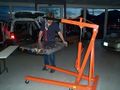
Battery pack lifted out of vehicle
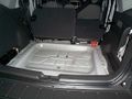
Trunk after the battery was removed


To open the battery:
- You need a #35 security Torx driver, and a #35 Torx driver
- Remove all the screws in the 2 top covers:
- Cover over the fans
- Cover over the batteries and electronics
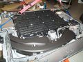
Battery pack opened, rear view
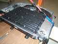
Battery pack opened, front view


Component locations

The battery includes (as seen when in the vehicle):
- Air blowers in the rear compartment
- NiMH cells in the center
- 2 layers of cells
- each layer in a left and right group
- each group has 13 columns of 5 cells in series
- total: 2 * 2 * 13 * 5 = 260 cells
- pack voltage: 1.3 V * 260 = 338 V
- controller on the right side
- contactors and HV connector on the right-front corner
- safety plug on the left-right corner
- the Converter on the left side
Block diagram

This block diagram shows the main components of the battery pack, and how they interface to the vehicle
- The NiMH cells store energy
- The battery controller controls the battery pack
- It communicates with the vehicle through the CAN bus
- It monitors the air intake temperature, it controls the intake air flow and source, and it drives to DC blowers to blow air into the cells
- It monitors the cells' voltage, including in intermediate points of the pack ("taps")
- ...
- The DC-DC converter receives power from the 12 V battery and boosts it up to 300 V, to charge the traction battery when it's dead and the user presses the Jump Start button (by the driver's left foot)
- The Safety Disconnects opens the pack mid-voltage
- The HV Output section
- It has a connector with 2 high-current contacts to connect the battery voltage to the vehicle
- It has a pair of wires to determine if that connector is connected or not
- It has contactors (high power relays) to connect or isolate the pack voltage
- The blower compartment has 2 DC blowers to blow air into the cells
Wiring diagram

This wiring diagram shows how the components of the battery pack are wired together.
- High voltage wires are red.
- Connectors are marked with their color and the number of positions
- Sets of wires are shown together. The slash at one end indicates the number of wires
- The function of sets of wires is shown above the wire
- The wire colors are shown below the set of wires
- Shaded squares indicate that wires are bundled together
- The orientation of the components is shown as seen when looking from the hatch
This reverse engineering drawing is not guaranteed to be accurate and is offered as-is. Please direct corrections to DavideAndrea.
Connectors

The battery has 3 connectors, with a total of 34 wires:
- C4227A - 28 wires - control
- C4227B - 2 wires - low power HV to the AC/DC converter
- C4227C - 4 wires - traction HV, interlock signals
AC/DC converter connector: C4227B


Pin-out. Looking into cable (left) and looking into battery (right)
The AC/DC converter connector has 2 circuits, with the following names and functions.
| Group | Ckt | Pin(s) | Ext. color | Int. color | Name | Function | Notes | |
| AC/DC converter in | 3000 | 1 | Vio | Red | AC/DC in+ | To connect a 115 Vac charger for the traction battery? | Ends in hood, by coolant tanks, unconnected and capped | ?? |
| 3001 | 1 | VioOrg | Blk | AC/DC in- | ?? |
This connector is on one end of a cable. The other end of the is cable capped, under the hood, on the right, in front of the 2 coolant tanks, fastened to its own harness.
I don't know what is supposed to go in it: some option? I don't know if this is an input or an output. The name (A/C converter), the fact that inside the traction battery the wires are black and red, and the relatively small size of the wires in the cable outside the battery, suggest that it's for a high-voltage, low current, traction battery charger. Maybe Ford provides a box, with just a bridge rectifier, 115 Vac in and 180 Vdc out, to charge the traction battery from the wall. D'de
Control connector: C4227A


Pin-out. Looking into cable (left) and looking into battery (right)
The big control connector has 24 circuits, with the following names and functions.
| Group | Ckt | Pin(s) | Ext. color | Int. color | Name | Function | Notes | |
| 12V pwr | 57 | 35,36,37 | LtgrnBlk | Blk | Ground | Power ground | OK | |
| 570 | 30,31 | BlkWht | BlkWht | Ground | Signal ground | OK | ||
| 3800 | 4,5,6 | LtgrnBlk | Red | +12 V | Power +12V | Always on | OK | |
| 16 | 10,11 | +12 V | RedLtgrn | RedBlu | Low power +12V | Always on | OK | |
| 3206 | 19 | LtgrnYel | TanRed | Voltage supplied in Start and Run | Receives 12 V when the ignition switch is in either the On or Start positions (even if engine is not running) | From the ignition switch. Overload protected | OK | |
| 3997 | 14 | Dkgrn | Tan | Power sustain relay out | Receives 12 V when the ignition switch is in either the On or Start positions (even if engine is not running) and for 2 seconds after the ignition is turned off | Fed by the Powertrain Control Module's Power Relay, located in the Battery Junction Box. The Powertrain Control Module is located under the hood, in the rear-center | OK | |
| Air intake | 3703 | 21 | BrnWht | BlkBrn | Battery compartment thermistor signal | Senses air intake temperature | All are located inside the column at the rear-left corner of car, inside air intake ducts | n.a. |
| 3704 | 25 | DkgrnWht | WhtBlk | Battery compartment thermistor return | n.a. | |||
| 698 | 34 | Red | RedBlu | Mode door actuator motor + | Moves a flap controlling air flow | n.a. | ||
| 699 | 26 | Org | BlkYel | Mode door actuator motor - | n.a. | |||
| 1129 | 17 | BrnWht | RedGRn | Mode door actuator potentiometer + | Senses position of flap | n.a. | ||
| 1130 | 20 | PnkLtgrn | BluBlk | Mode door actuator potentiometer wiper | n.a. | |||
| 1128 | 24 | GryLtBlu | BlkWht | Mode door actuator potentiometer - | n.a. | |||
| 698 | 34 | Red | RedBlu | Zone Valve | Solenoid selecting air source | n.a. | ||
| CAN BUS | 1908 | 29 | Wht | YelRed | High speed CAN bus + | Communicates with vehicle | See CAN section below for messages | OK |
| 1909 | 28 | Blk | YelWht | High speed CAN bus - | OK | |||
| Jump start switch | 176 | 16 | PnkLtgrn | BrnWht | Jump start switch feed | When grounded, lets 12 V battery jump charge-up the traction battery a bit, through DC-DC converter in battery pack, enough to start the car | The switch is located to the left of the driver's left ankle, behind a black plastic panel | OK |
| 179 | 12 | OrgRed | GrnBlk | Jump start switch illumination + | When at 12 V, it lights-up the switch | OK | ||
| Emergency control | 3003 | 8 | VioWht | Tan | Battery power off signal | 0-12 V square wave, 50% duty cycle, generated by battery. If all OK, 2 Hz. If problem, 5 Hz? | The Power Train Control Module is located under the hood, in the rear-center | OK |
| 877 | 7,23 | Wht | RedBlk | Fuel pump feed / Inertia Sw input | Normally receives 12 V when the ignition switch is in either the On or Start positions (even if engine is not running) and for 2 seconds after the ignition is turned off; no voltage when the ignition is off, or in case a crash opens an inertia switch | The High Voltage Cutoff switch is located in the right-rear column of the car | OK | |
| 212 | 27 | Dkblu | BlkBlu | Immediate shutdown 1 | The Transaxle Control Module tells the battery to remove power to the vehicle? | The Transaxle Control Module is under the hood, in the center, to the left of the box labeled "HYBRID" | OK | |
| 213 | 13 | DkbluYel | BlkRed | Immediate shutdown 2 | OK | |||
| Unused | n.a. | 18 | n.a. | TanRed | ??? | ??? | Connected to controller, not used in vehicle | ?? |
| 32 | YelBlk | ?? |
Notes
- Green OK: function is understood and confirmed
- Red ??: function is not understood, or not yet confirmed
- Gray n.a.: PHEV conversion can work without this function
HV connector: C4227C


Pin-out. Looking into cable (left) and looking into battery (right)
The HV connector has 4 circuits, with the following names and functions.
| Group | Ckt | Pin(s) | Ext. color | Int. color | Name | Function | Notes | |
| HV | 3180 | + | Org | n.a. | HV+ | Battery power | To Transaxle Control Module | OK |
| 3181 | - | Org | HV- | OK | ||||
| Interlock | 3130 | 1 | Gry | Blu | Traction Battery Control Module Interlock + | Detects if HV connector is mated. The battery and the Transaxle Control Module both look at the voltage at these pins. | To Transaxle Control Module | OK |
| 3181 | 2 | Red | Wht | Traction Battery Control Module Interlock - | OK |
Electronic Components
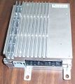
The controller
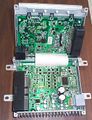
The controller, opened. The low voltage board is at the bottom, the high voltage one at the top
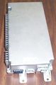
The Jump Start Converter


Battery HVAC system


The HVAC system controls the temperature of the NiMH cells in the traction battery.
Its components are located:
- in the rear-left column
- in the traction battery itself
When used in a closed loop, air flows:
- from the empty spaces in the battery pack
- out of the rear-most grille in the rear-right corner of the battery pack
- into a duct in the rear-right column of the vehicle
- up the rear duct in that colums
- through the Mode Door that controls the air flow (unconfirmed)
- through the Zone Valve that selects the air source (unconfirmed)
- forward through a heat exchanger
- down the front duct
- out of the rear-right column
- into the front-most grille in the rear-right corner of the battery pack
- into the battery pack
- into 2 ducts, one for each blower
- into 2 blowers, one for each duct
- into each set of cells (left set for left blower, right for right)
- through the cells and into the empty spaces in the battery pack
- completing the cycle
The heat exchanger is either chilled by the vehicle's air conditioning system, or heated by the vehicle's engine coolant
When using outside air:
- air is taken from a vent in the rear-right window
- down a duct
- flows through an air filter
- through the Mode Door
- into the heat exchanger
- then following the same path as above
Now that extra air has been taken into the system, air has to be let out of it
- air from the pack flows into the rear duct
- the Zone Valve opens, letting out air from the rear duct into the open space in rear-right column
- from there, air flows into the rear storage area
To monitor the temperature, thermistors are placed:
- 1 in the rear-right ducts
- 2 by the blowers, one for each blower
- 2 in the left block of cells, 2 in the right block (unconfirmed)
To control the air flow and temperature:
- the blower's speed is variable
- the Mode Door's position is continuously variable from closed to fully open
- the Zone Valve selects the air source
CAN bus messages
The battery communicates to the rest of the vehicle through the CAN bus. The
- Kvaser has a simple explanation of the CAN bus.
- wikipedia article on the CAN bus
CAN Tools
- A generic adapter between the CAN-bus and a PC. It is convenient to use a USB port, though the serial or parallel or Ethernet port may be used as well. Examples of USB adapters:
- Peak's PCAN-USB also sold as the GridConnect's GC-CAN-USB
- Note: disconnecting this product's USB cable seems to create significant problems for Windows XP (immediate shut-down, or even the "blue screen of death"). You must use the system tray's "Remove hardware" icon first.
- Grifo's CANUSB
- Systec's USB-CANmodul
- CAN232 is a CAN to RS232 device used by Attila Vass with his early My CAN Project.
- The CAN-View should not be confused with this CANview product (notice no dash in the name), which is a CAN to RS232 device.
- Peak's PCAN-USB also sold as the GridConnect's GC-CAN-USB
- These adapters have a DE-9 DSUB connector, so you'll also need an adapter to the Prius' OBD connector. For example:
- The Prius' OBD (On Board Diagnostics) connector is located under the dashboard, below and to the right of the steering wheel, facing down. A.k.a.: Data Link Connector 3 (DLC3)
- Alternatively, tap into the CAN bus directly. Use a short cable to the CAN adapter.
- CAN -: black wire
- CAN +: white wire
- GND - chassis
CAN bus protocol
- The CAN bus is active only when the vehicle is in on (Start or Run position of the ignition key), and for a few seconds after the vehicle is turned off.
- baud rate: 500 kbits/s (if you use the wrong rate, the vehicle will complain and store a DTC fault until the DTC codes are cleared)
- Standard: CAN 2.0A ("standard CAN", 11-bit identifier)
- Remote frames: not used
- this means all the data are volunteered and none are requested; that is, that every component on the vehicle broadcasts its data periodically; no component puts out requests for data
CAN bus messages
The CAN bus has only 24 messages.
This screen capture was taken with the ignition on On, engine off, on Hybrids Plus' Escape.

Battery CAN messages
These are the messages generated by the battery.
The Battery ECU (Electronic Control Unit) broadcasts the following messages. In this table, numbers in parenthesis (#) refer to the notes just below the table. Names in parenthesis are hunches.
| ID (hex) | Period [ms] (1) |
No of data bytes |
byte 0 | byte 1 | byte 2 | byte 3 | byte 4 | byte 5 | byte 6 | byte 7 |
| 300h | 10 | 5 | Current (2) | Voltage (3) | Flags (4) | 00h | ||||
| 310h | 100 | 7 | constant (7) | constant (8) | constant (9) | constant (10) | Temperature (11) | (Charge Limit) (12) | (Discharge Limit) (13) | |
| 320h | 100 | 5 | 00h | 00h | Flags (15) | Flags (16) | SOC (17) |
| ||
Notes:
- h = hex value; d = decimal value; b = binary value;
1) How often this message is repeated
2) Battery current. Raw reading, relative to reading at 0 current (typically 0600h), positive when current is sourced out of the battery. 12 bits? Units: 25 mA. Range (if 12 bits & 25 mA): 100 A out to 35 A in. Examples (assuming that at 0 current the reading is 0600h):
- 0FC4h: 100 A out
- 0790h: 10 A out
- 0628h: 1 A out
- 0600h: 0 A
- 05D8h: 1 A in
- 0479h: 10 A in
- 0000h: 38 A in
3) Battery voltage. Relative to 180 V. Units: V. Range seen: 312 to 366 V. Examples:
- 78h: 300 V
- 96h: 330 V
4) Byte of flags. If the specified item is active, the bit is 1. Else, it is 0. 0 = unused or unknown bit.
| bit | 7 | 6 | 5 | 4 | 3 | 2 | 1 | 0 |
| function | 0 | 0 | 0 | Safety plug removed | 0 | Contactors on | Precharge relay on | 0 |
6) Byte of flags. If the specified item is active, the bit is 1. Else, it is 0. 0 = unused or unknown bit.
| bit | 7 | 6 | 5 | 4 | 3 | 2 | 1 | 0 |
| function | Safety plug removed | HV connector unplugged | 0 | 0 | 0 | 0 | 0 | 0 |
7) unknown. Always 8Ch
8) unknown. Always 78h
9) unknown. Always 50h
10) unknown. Always 3Ch
11) Pack temperature, relative to - 90C. Units: C. Insufficient data points to confirm this. Examples:
- 104 = 14 C
- 90 = 0 C
- 82 = -8 C
12) Charge Current Limit or something related to temperature? When first turned on, this item starts at a value, then drifts down to another value and stops. Turn off, turn on, and the item restarts at the same value where it started before. The values are very similar to the Temperature values. Needs more study.
13) Probably Discharge Current Limit. Units: A? Range seen: 75 to 155. Related to the actual State of Charge according to the graph on the right, and these approximate formulas:
- SOC< 138: value = 1.57 * SOC- 70
- 138 < SOC< 157: value = 103 + 0.33 * SOC
- SOC> 157: value = 155
15) Byte of flags. If the specified item is active, the bit is 1. Else, it is 0. 0 = unused or unknown bit.
| bit | 7 | 6 | 5 | 4 | 3 | 2 | 1 | 0 |
| function | Safety plug removed | HV connector unplugged | 0 | 0 | 0 | 0 | 0 | 0 |
16) Byte of flags. If the specified item is active, the bit is 1. Else, it is 0. 0 = unused or unknown bit.
| bit | 7 | 6 | 5 | 4 | 3 | 2 | 1 | 0 |
| function | 0 | 0 | 0 | 0 | 0 | 0 | 0 | All OK: HV connector is plugged, Safety Plug is in |

17) State of Charge. Units: mAh. Range seen: 93 to 207 mAh. When stopped, and charging, the engine stops when the SOC level reaches DEh (111 mAh) and starts when the SOC drops to BDh (189 mAh)
| General Disclaimer: (HV) (DC) injury or death hazard, use at your own risk, may void warranty. |
|---|
|
HV (High Voltage) DC (Direct Current) Warning: Traction Battery Packs, Motors, Chargers, and other HV sources could cause serious injury or death if proper precautions are not taken while working on or around such High Voltage Direct Current sources. Use this information at your own risk: There is no warranty expressed nor implied and we are not liable for any of your past, present, nor future actions. Even should you perform these modifications to the letter you could still damage any number of components in your vehicle causing it to no longer function. Even if it appears to function properly your actions may cause it to self destruct with collateral damage to surrounding properties other than your vehicle. By utilizing these ideas and instructions in an attempting to enhance national security, reduce gas consumption, vehicle "emissions", your carbon footprint, or smog, you do so at your own risk & peril. Warranty: In performing some of these modifications you may void your warranty with the vehicles manufacturer. See also our My wiki:General disclaimer |