|
General Disclaimer: (HV) (DC) injury or death hazard, use at your own risk, may void warranty. |
Difference between pages "PriusPlus-Theory" and "Prius OEM fan control"
(rm Category:Hybrid) |
|||
| Line 1: | Line 1: | ||
| − | |||
| − | |||
{{TOCright}} | {{TOCright}} | ||
| − | |||
| − | |||
| − | |||
| − | + | Cooling for the [[Toyota Prius]] is done with simple air flow from a squirrel cage type fan capable of drawing about 6 amps for ample air flow. Though the Prius almost never runs the fan at full speed. In fact the fan isn't even powered until the battery temperature reaches ''?96°F'' and doesn't attempt to cool aggressively by speeding up the fan until the temperature is well above ''?120°F''. This is perfectly acceptable for normal operation but for certain methods used to convert the car into a [[Prius PHEV]] more cooling is desirable. There are a number of reasons such as: | |
| + | * The [[Prius EV Mode]] is not allowed if the battery is above 107°F. | ||
| + | * The [[Battery Pack Configurations#Hybrid|Hybrid Battery Pack Configuration]] tends to warm the OEM battery during heavy use due to the charge current which is applied. | ||
| + | * High temperatures limit the Charge Current Limit leading to something similar to the [[State Of Charge Manipulation#Charge Limit Conundrum|CCL Conundrum]]. | ||
| − | + | So for these reasons such conversions have devised methods for overriding the OEM Fan control so that the fan can be run faster in order to keep the battery at a lower target temperature. This may also be handy for stock cars in hot climates and can be easily implemented as a stand alone modification without the full PHEV conversion. Here is how OEM battery fan control is dealt with for a pair of PHEV conversions: | |
| + | * [[PriusPlus-Theory#OEM Battery Fan Controls]] | ||
| + | ** [[PriusPlus-Instructions#OEM Battery Fan Control Tap]] | ||
| + | ** [http://autos.groups.yahoo.com/group/eaa-phev/message/688 Y!:Prius OEM battery fan control info] | ||
| + | * A portion of the [[PiPrius conversion process#Interlock Box]] schematics [[:Image:Interlockschematic.png]] handles OEM fan control for the [[PiPrius]] project. | ||
| − | + | As an alternative to cutting Prius wires you can purchase the following OEM battery plug and mating pins, though they are not inexpensive: | |
| + | * OEM battery fan plug pins: Toyota P/N 82998-12380 | ||
| + | * OEM battery fan plug mating pins: Toyota P/N 82998-12370 | ||
| − | + | == Stand along OEM fan control == | |
| + | Using the same method employed by the PiPrius conversions you can build a simple stand alone circuit capable of overriding the OEM fan control and running the fan at full speed instead which rapidly removes heat from the OEM battery pack. | ||
| − | The | + | === Parts List === |
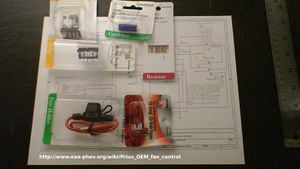
| + | [[Image:DSC00378.JPG|thumb|right|The parts, note that a smaller capacitor was used.]] | ||
| + | * Shielded blade type crimp connectors (light blue) | ||
| + | * 16 awg Wire (Green, Violet, Red, Black, and White) | ||
| + | * Heavy fence wire, or a metal coat hanger | ||
| + | * Eyelet crimp connector (Red, large eyelet) | ||
| + | * A DPDT Relay and matching socket (10A contacts) | ||
| + | * Two (2x) 220ohms 1/4 watt resistors | ||
| + | * A 330uF Alum capacitor (error toward higher values) | ||
| + | * 7.5A fues and fuse holder | ||
| + | * Hot glue gun with high temp glue | ||
| − | === | + | === Construction === |
| − | + | {{Disclaimer}}{{Clear}} | |
| − | * | + | [[Image:DSC00372.JPG|thumb|right|Splicing OEM fan circuit wire near fan connector.]] |
| − | ** | + | [[Image:DSC00381.JPG|thumb|right|The heavy wire used for mounting.]] |
| − | + | [[Image:DSC00426.JPG|thumb|right|Fully wired, just need to insulate.]] | |
| − | + | [[Image:DSC00434.JPG|thumb|right|Used hot glue to insulate.]] | |
| − | + | [[Image:DSC00387.JPG|thumb|right|Mounted in car near OEM fan.]] | |
| − | + | # You will need to cut the OEM can wires between the support clip and the plug which attaches to the fan. | |
| + | #* There are two green and two violet wires, attach insulated blade crimp connectors to the OEM wires in such a manner that they can be plugged back into their original configuration. Use the same gender on the wires leading to the fan, and the other gender on the other wires which lead to the OEM CPU. | ||
| + | # The Heavy eyelet is used as a ground point and for structural support when mounting the circuit. | ||
| + | #* Use heavy fence wire, or a pliable metal coat hanger (not so heavy that it's difficult to bend). Wrap the wire around the relay socket twice leaving an two inches or so of excess twisting out from one side. You will attach the ground wire and the large eyelet crimp connector to the end of the heavy wire for mounting it to a ground point. | ||
| + | #* Use hot glue to ensure that the wire wrapped around the relay socket can't work it's way off due to vibration. | ||
| + | #* You may also choose to solder the eyelet to the ground wire and heavy wire after crimping. | ||
| + | # Solder the short black ground wire to one of the coil pins of the relay socket and also (or another length) to the NO (Normally Open) pin of one of the relays throws. | ||
| + | # Solder a 12" length of Violet wire to the swinger pin on the same throw. To the other end crimp a blade connector which will mate with the connector leading to the fans Violet wire. | ||
| + | # Solder a long length of White wire to the remaining coil pin on the relay socket, this will be energized with +12v to enable the fan control override so you may want it to reach the drivers seat area. | ||
| + | # Solder a 24" length of Red wire which must also be fused to the unused NO pin of the other throw. This wire will be attached to the +12v accessory battery to power the OEM battery fan. | ||
| + | # Solder a 12" length of Green wire to the unused swinger pin. To the other end crimp a blade connector which will mate with connector leading to the fans Green wire. | ||
| + | # To the remaining two NC (Normally Closed) pins you will need to attach the two 220 ohm 1/4 watt resistors and the 330 uF Alum (Polarized) capacitor, these will fool the Prius CPU into thinking that there is still a fan attached when we disconnect the real fan from it. | ||
| + | ## Solder a 12" length of Green wire and one leg of one of the resistors to the Green NC pin (The throw with the Green and Red wires already attached). To the other end of the wire crimp a blade connector which will mate with connector leading to the CPUs Green wire. | ||
| + | ## Solder a 12" length of Violet wire, one leg of the other resistor, and the negetive(-) leg of the capacitor to the Violet NC pin (The throw with the Violet and ground wires already attached. To the other end of the wire crimp a blade connector which will mate with connector leading to the CPUs Violet wire. | ||
| + | ## Solder the remaining three legs, two resistor legs and positive(+) capacitor leg together, they should not touch any other points. | ||
| + | ## Use an insulating material such as hot glue to insure that none of the pins nor components soldered to the relay socket can be touched. We don't want anything to get grounded once it's installed. | ||
| + | # Install by securing the eyelet under the nut which holds a metal bracket with a wire disconnect attached just above the OEM cooling fan. Plug the Green and Violet wires into their proper locations between the CPU and Fan at the splice location. Attach the fused +12v wire to the accessory battery positive(+) post. | ||
| + | # Now any time that the White wire is supplied with +12v the OEM fan should roar to life at full power. You can now program your [[CAN-View]] to turn on the fan at above some temperature such as 95°F. Or you can simply attach the wire to a toggle switch that you can turn on and off, but be sure that the switch is attached to an acc/run +12v source such that if you leave the switch on when the car is off it won't continue to run and drain your accessory battery. | ||
| − | === | + | === Photos Schematics === |
| − | + | [[Image:DSC00433.JPG|thumb|right|The circuit.]] | |
| + | * ___ * | ||
| + | / _ \ | ||
| + | ( (_) ) | ||
| + | Ground\___/wire to eyelet | ||
| + | ___|X | ||
| + | | X ___________________________Fan {Violet} | ||
| + | |___X__|______ __________________CPU {Violet} | ||
| + | ----|---X--|-----|-----|----- | ||
| + | | | | | | | | ||
| + | | O O O O____|__________ | ||
| + | | | | |- | ||
| + | | coil swing NO NC | R2 C1 | ||
| + | | ____|__R1__|__|+ | ||
| + | | O O O O | | ||
| + | | | | | | | | ||
| + | ----|------|-----|-----|----- | ||
| + | | | | |_________________CPU {Green} | ||
| + | | |_____|____________________Fan {Green} | ||
| + | | | | ||
| + | | +12v fused {Red} | ||
| + | +12 to enable {White} | ||
| + | *'''Relay Socket Wiring''' * | ||
| − | + | [[Category:PHEV]] | |
| − | + | [[Category:Prius]] | |
| − | + | [[Category:PiPrius]] | |
| − | + | [[Category:PriusPlus]] | |
| − | |||
| − | |||
| − | |||
| − | |||
| − | |||
| − | |||
| − | |||
| − | |||
| − | |||
| − | |||
| − | |||
| − | |||
| − | |||
| − | |||
| − | |||
| − | |||
| − | |||
| − | |||
| − | |||
| − | |||
| − | |||
| − | |||
| − | |||
| − | |||
| − | |||
| − | |||
| − | |||
| − | |||
| − | |||
| − | |||
| − | |||
| − | |||
| − | |||
| − | |||
| − | |||
| − | |||
| − | |||
| − | |||
| − | |||
| − | |||
| − | |||
| − | |||
| − | |||
| − | |||
| − | |||
| − | |||
| − | |||
| − | |||
| − | |||
| − | |||
| − | |||
| − | |||
| − | |||
| − | |||
| − | |||
| − | |||
| − | |||
| − | |||
| − | |||
| − | |||
| − | |||
| − | |||
| − | |||
| − | |||
| − | |||
| − | |||
| − | |||
| − | |||
| − | |||
| − | |||
| − | |||
| − | |||
| − | |||
| − | |||
Revision as of 09:27, 9 October 2007
Cooling for the Toyota Prius is done with simple air flow from a squirrel cage type fan capable of drawing about 6 amps for ample air flow. Though the Prius almost never runs the fan at full speed. In fact the fan isn't even powered until the battery temperature reaches ?96°F and doesn't attempt to cool aggressively by speeding up the fan until the temperature is well above ?120°F. This is perfectly acceptable for normal operation but for certain methods used to convert the car into a Prius PHEV more cooling is desirable. There are a number of reasons such as:
- The Prius EV Mode is not allowed if the battery is above 107°F.
- The Hybrid Battery Pack Configuration tends to warm the OEM battery during heavy use due to the charge current which is applied.
- High temperatures limit the Charge Current Limit leading to something similar to the CCL Conundrum.
So for these reasons such conversions have devised methods for overriding the OEM Fan control so that the fan can be run faster in order to keep the battery at a lower target temperature. This may also be handy for stock cars in hot climates and can be easily implemented as a stand alone modification without the full PHEV conversion. Here is how OEM battery fan control is dealt with for a pair of PHEV conversions:
- PriusPlus-Theory#OEM Battery Fan Controls
- A portion of the PiPrius conversion process#Interlock Box schematics Image:Interlockschematic.png handles OEM fan control for the PiPrius project.
As an alternative to cutting Prius wires you can purchase the following OEM battery plug and mating pins, though they are not inexpensive:
- OEM battery fan plug pins: Toyota P/N 82998-12380
- OEM battery fan plug mating pins: Toyota P/N 82998-12370
Stand along OEM fan control
Using the same method employed by the PiPrius conversions you can build a simple stand alone circuit capable of overriding the OEM fan control and running the fan at full speed instead which rapidly removes heat from the OEM battery pack.
Parts List
- Shielded blade type crimp connectors (light blue)
- 16 awg Wire (Green, Violet, Red, Black, and White)
- Heavy fence wire, or a metal coat hanger
- Eyelet crimp connector (Red, large eyelet)
- A DPDT Relay and matching socket (10A contacts)
- Two (2x) 220ohms 1/4 watt resistors
- A 330uF Alum capacitor (error toward higher values)
- 7.5A fues and fuse holder
- Hot glue gun with high temp glue
Construction
| General Disclaimer: (HV) (DC) injury or death hazard, use at your own risk, may void warranty. |
|---|
|
HV (High Voltage) DC (Direct Current) Warning: Traction Battery Packs, Motors, Chargers, and other HV sources could cause serious injury or death if proper precautions are not taken while working on or around such High Voltage Direct Current sources. Use this information at your own risk: There is no warranty expressed nor implied and we are not liable for any of your past, present, nor future actions. Even should you perform these modifications to the letter you could still damage any number of components in your vehicle causing it to no longer function. Even if it appears to function properly your actions may cause it to self destruct with collateral damage to surrounding properties other than your vehicle. By utilizing these ideas and instructions in an attempting to enhance national security, reduce gas consumption, vehicle "emissions", your carbon footprint, or smog, you do so at your own risk & peril. Warranty: In performing some of these modifications you may void your warranty with the vehicles manufacturer. See also our My wiki:General disclaimer |
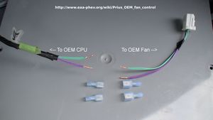
- You will need to cut the OEM can wires between the support clip and the plug which attaches to the fan.
- There are two green and two violet wires, attach insulated blade crimp connectors to the OEM wires in such a manner that they can be plugged back into their original configuration. Use the same gender on the wires leading to the fan, and the other gender on the other wires which lead to the OEM CPU.
- The Heavy eyelet is used as a ground point and for structural support when mounting the circuit.
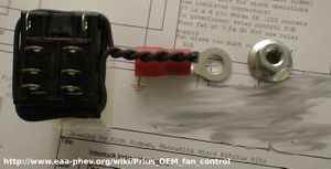
- Use heavy fence wire, or a pliable metal coat hanger (not so heavy that it's difficult to bend). Wrap the wire around the relay socket twice leaving an two inches or so of excess twisting out from one side. You will attach the ground wire and the large eyelet crimp connector to the end of the heavy wire for mounting it to a ground point.
- Use hot glue to ensure that the wire wrapped around the relay socket can't work it's way off due to vibration.
- You may also choose to solder the eyelet to the ground wire and heavy wire after crimping.
- Solder the short black ground wire to one of the coil pins of the relay socket and also (or another length) to the NO (Normally Open) pin of one of the relays throws.
- Solder a 12" length of Violet wire to the swinger pin on the same throw. To the other end crimp a blade connector which will mate with the connector leading to the fans Violet wire.
- Solder a long length of White wire to the remaining coil pin on the relay socket, this will be energized with +12v to enable the fan control override so you may want it to reach the drivers seat area.
- Solder a 24" length of Red wire which must also be fused to the unused NO pin of the other throw. This wire will be attached to the +12v accessory battery to power the OEM battery fan.
- Solder a 12" length of Green wire to the unused swinger pin. To the other end crimp a blade connector which will mate with connector leading to the fans Green wire.
- To the remaining two NC (Normally Closed) pins you will need to attach the two 220 ohm 1/4 watt resistors and the 330 uF Alum (Polarized) capacitor, these will fool the Prius CPU into thinking that there is still a fan attached when we disconnect the real fan from it.
- Solder a 12" length of Green wire and one leg of one of the resistors to the Green NC pin (The throw with the Green and Red wires already attached). To the other end of the wire crimp a blade connector which will mate with connector leading to the CPUs Green wire.
- Solder a 12" length of Violet wire, one leg of the other resistor, and the negetive(-) leg of the capacitor to the Violet NC pin (The throw with the Violet and ground wires already attached. To the other end of the wire crimp a blade connector which will mate with connector leading to the CPUs Violet wire.
- Solder the remaining three legs, two resistor legs and positive(+) capacitor leg together, they should not touch any other points.
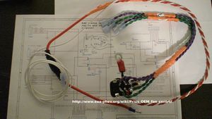
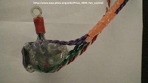
- Use an insulating material such as hot glue to insure that none of the pins nor components soldered to the relay socket can be touched. We don't want anything to get grounded once it's installed.
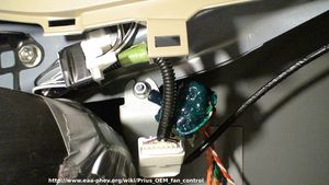
- Install by securing the eyelet under the nut which holds a metal bracket with a wire disconnect attached just above the OEM cooling fan. Plug the Green and Violet wires into their proper locations between the CPU and Fan at the splice location. Attach the fused +12v wire to the accessory battery positive(+) post.
- Now any time that the White wire is supplied with +12v the OEM fan should roar to life at full power. You can now program your CAN-View to turn on the fan at above some temperature such as 95°F. Or you can simply attach the wire to a toggle switch that you can turn on and off, but be sure that the switch is attached to an acc/run +12v source such that if you leave the switch on when the car is off it won't continue to run and drain your accessory battery.
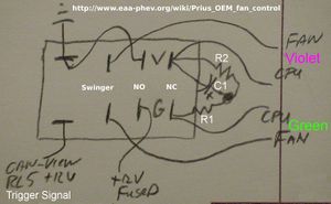
Photos Schematics
*      ___                                            *
      / _ \
     ( (_) )
Ground\___/wire to eyelet
    ___|X
    |   X  ___________________________Fan {Violet}
    |___X__|______     __________________CPU {Violet}
----|---X--|-----|-----|-----
|   |      |     |     |    |
|   O      O     O     O____|__________
|                           |      |  |-
|  coil  swing   NO    NC   |     R2  C1
|                       ____|__R1__|__|+
|   O      O     O     O    |
|   |      |     |     |    |
----|------|-----|-----|-----
    |      |     |     |_________________CPU {Green}
    |      |_____|____________________Fan {Green}
    |            |
    |        +12v fused {Red}
+12 to enable {White}
*Relay Socket Wiring                                  *
