|
General Disclaimer: (HV) (DC) injury or death hazard, use at your own risk, may void warranty. |
PriusPlus-Instructions
| Click show for a short list of the current PHEV conversion and kit options for the Toyota Prius. |
|---|
|
For Prius conversion details see the Prius PHEV article and comparisons table.
|
|
--={ Project Overview
}={ 2007 Maker Faire
}={ Theory
}={ Instructions
}={ Parts List
}={ RawData
}={ Latest News
}=--
|
|---|
|
--={ Historic }={ Battery }={ Schematics }={ PseudoCode }={ Photos }=-- |
 Team Photo from the PriusPlus conversion of Sven's Prius from Nov 2006. This is the home of the PRIUS+ PHEV DIY (Do-it-Yourself) documentation. These pages are currently anonymously editable, which may change in the future. Please feel free to use the Discussion page for general discussion and commentary on the main article. If you would like to add to an existing section use the "edit" link near that topic's heading. Don't forget to use the Summary field to describe your changes. While editing use the "Show Preview" button to make sure your changes look like you expect them to, before you click "Save Page". |
Contents
- 1 Choosing a Mounting Method
- 2 CAN-View & EV Mode button
- 3 Battery Tray Construction
- 4 Battery Box Supports (Classic Method)
- 5 Battery Box Supports (Alternative Method)
- 6 Battery Box Top
- 7 Control Board
- 8 LED Board
- 9 Electronic/Electric Sub Part Construction
- 10 Electronics Tray (Classic Method)
- 11 Electronics Box (Alternative)
- 12 Installation Into the Prius
- 13 Disassembling the Prius
- 13.1 Remove user-removable parts
- 13.2 Battery Carpet & Seat Removal
- 13.3 Side panel Removal
- 13.4 Routing CAN-View cables to trunk
- 13.5 Air Vents (Classic Method)
- 13.6 Installing the Outlet Box (Classic Method)
- 13.7 Install Charger / Electronics Box (Alternative Method)
- 13.8 Install Batt. Box Foundation / Electronics Tray (Classic Method)
- 13.9 Install Battery Box Foundation (Alternative Method)
- 13.10 OEM Battery Fan Control Tap
- 13.11 Safety Warning & Tips
- 13.12 Tapping into OEM Battery
- 13.13 Tap into the 12v Accessory Battery
- 13.14 Reassemble the Prius Trunk
- 13.15 Connecting the PbA batteries
- 13.16 Optional Bumper Mounted Inlet
- 13.17 Optional Mounted Cord Reel (Classic Method)
- 13.18 The First Tests
- 13.19 Programming CAN-View/Control Board
Welcome to the PriusPlus Do-It-Yourself documentation. Below you will find details on converting your 2004-2007 Prius to a plug-in hybrid via the PriusPlus method. The documentation is laid out in three parts. The PriusPlus gives an overview of the conversion and lists benefits, limitations and normal operating behavior. PriusPlus-Theory gives details the theory behind how the conversion works. The PriusPlus-Instructions page (this page) gives detailed, ordered instructions on how to convert your Prius yourself.
Choosing a Mounting Method
Before getting too far, you will need to decide on a mounting method. Currently, there are 2 methods, each with their benefits. The majority of the instructions are the same for both methods, however, some sections will be labeled as "classic mounting method" and others as "alternative mounting method" and contain instructions for the specific method.
Classic Mounting Method
The "Classic" method is the classic CalCars style. The spare tire well is largely unchanged, the batteries are placed in the very rear of the trunk, an electronics tray is placed in front of the batteries and the charger is placed in the left cubby hole (the carpeting in the cubby hole is cut back.) This method allows for easy access to all the electronics, including the charger.
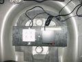
Classic method - spare tire well
Classic method - charger
Finished trunk (top view)


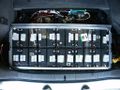
Alternative Mounting Method
The "Alternative" method seeks to maximize usable trunk space and minimize visible changes. With this design, the batteries are moved as far forward as possible and the supporting electronics and charger are located in the spare tire well. The batteries stick up through the false floor, but are flush with the Prius's floor. Most of the high voltage electronics are isolated from the low voltage electronics, however some of the high voltage electronics and the charger are more difficult to access because they are below the batteries (they tend to be the more reliable parts, however.) The low voltage electronics are easily accessible.
Spare tire well
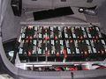
Location of Batteries
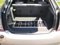
Finished Product


CAN-View & EV Mode button
Overview
Start by installing CAN-View. CAN-View gives you insight into how the Prius works and it is best to have it installed before doing the conversion. Please see PriusPlus-Theory for more information on what CAN-View and Prius EV Mode Button do and how they work.
You will need to purchase CAN-View from hybridinterfaces.ca. There are currently 4 versions of CAN-View available. Version 3 and 3plus require an '04 or '05 Prius and makes use of the built in display (or MFD) while Version 4 and 4plus work with an 04-07 Prius but requires an external touchscreen (since the built in touchscreens were changed in the '06 model and are no longer compatible.) Version 4 has the PHEV relays built onto the main board, while version 3 has an extra optional PHEV relay board, which is required for this conversion. Version 3plus and 4plus feature a smart relay board which can interact with battery regulators. At the present, the PriusPlus conversion method does not make use of the smart relay features in the "plus" models.
Installation
Approx. time requirement: 45 minutes - 2 hours
The CAN-View is installed differently depending on whether or not your car is equipped with in-dash navigation. Detailed instructions with photos are available with NAV or without NAV. It is best to install and route the wires for the Prius EV Mode Button at the same time since they both require disassembling the dash.
ToDo the following section is shared with the PiPrius_conversion_process#CAN-View_.26_EV_Mode_Button documentation. Any changes should be generic enough to satisfy both, place project specific notes above or below it. Another set of instructions may be needed for the CAN-View Version 4 which does not integrate with the OEM MFD and gets power directly from the OBDII port, Prius CAN View V4 Mounting options at PriusChat.com covers various ways of mounting the second touch screen.
Installing the CAN-View Version 3 and Prius EV Mode Button both involve disassembling the same areas of the Prius so will be covered here at the same time. You should also be familiar with these cv#reference materials.
- cv1. File:Stereo Accessory Install Guide 04 Prius v1.03.pdf from http://www.chrisdragon.com
- cv2. File:PriusXMradio3.2.pdf from https://www.metrotpn.com
- cv3. File:CAN-View installNONAVwt.pdf Adapted from http://www.hybridinterfaces.ca/installNONAV.html
- cv4. File:CAN-View installWNAVwt.pdf Adapted from http://www.hybridinterfaces.ca/installWNAV.html
- cv5. File:Prius-evbutton-install.pdf from http://www.calcars.org/prius-evbutton-install.pdf
- cv6. File:FactoryEV.pdf from http://www.scubadivervideo.com/Files/factoryEV.pdf
We begin by disassembling the dashboard. cv1 cv2
- Remove the bottom cover of steering column
- Releasing the steering wheel adjustment handle and removing the silver screw.
- Turn steering wheel 90 degrees to right and left to remove black screws on each side.
- Remove the lower cover by carefully pulling down on lower half.
- Disconnect the headlamp flasher plug on left side of steering column.
- Remove plugs cover by unlocking two side tabs/clips.
- Remove 3 unused connector pins using a jeweler's screwdriver to disengage and slide them out.
- Optionally to use the headlamp flasher circuit as an EV Mode button:
- Solder some length?? of black wire to a new pin and use it to replace:
The Red(#11-B10) wire to preserve day time flashing function, will disable night time flashing.It has been discovered that this does not work properly as the red wire is used for both the high beam and flash functions when the lights are turned on, thus disabling high beams at night. Anyone who has implemented this option should reinstall the red wire, moving the ev-mode button wire to the violet wires location instead.- The Violet(#17-B4) wire to preserve night time flashing function, will disable day time flashing.
- Route new black wire along existing bundle then towards center console to later meet up with OBDII cable.
- Snap the cover back onto the flasher plug and reinsert into switch.
- Reassemble steering column, be sure everything is aligned properly.
- Remove lower glove box by squeezing the inside sides together to lower box below catches, then unclip the small piston from right side. Lower box until the lower joints detach from dash, remove pneumatic cylinder noting it's orientation.
- Remove passenger side silver air vent cover by pulling out from the bottom first. Next remove the small interior colored piece just below the vent piece by pulling straight out.
- If installing CAN-View Without Navigation: cv3
- Remove drivers side air vent cover, press down and pull out on top.
- Remove lower center console hump with 12v lighter power socket, remove barb from passenger side, pull out.
- Remove air vent at right side of MFD screen, open upper glove box to pull out vent.
- Remove lower drivers side interior colored dash panel, one black screw above hood release, one exposed behind drivers side vent.
- Remove black lower dash key fob panel, leave hanging with wires connected.
- Remove upper drivers side dash panel with power button, leave wires attached.
- Remove air vent at left side of MFD screen, the shift lever with remain in place, detach and slide park button forward through silver panel to expose and detach cable, then remove the panel and reattach the park button to it's cable to prevent errors during later tests.
- Remove 10mm bolts, one on each side of MFD screen, pull screen out sharply and rotate towards drivers side.
- Tap grey OEM wire for 12v power, top row 2nd from the left.
- Attach CAN-View video cable to MFD and power spade to tapped grey wire, run cable out directly behind screen.
- Connect CAN-View OBDII cable to OBDII port and route cable behind center console towards glove box along with headlamp flasher ev-mode button wire if installed.
- Test CAN-View, then reassemble center and drivers side of dash.
- CAN-View will be mounted under passenger seat, above JBL amplifier if present.
- If installing CAN-View With Navigation: cv4
- Route OBDII Cable around foot well and down drivers side door sill to underneath drivers seat. Route headlamp flasher ev-mode button wire if installed behind center console and glove box.
- Tap grey OEM wire from navigation unit for 12v power.
- Connect CAN-View video cables to navigation unit.
- Test and attach above and to rear of navigation unit.
- Solder new pin to some length?? of black wire, and optionally the black wire which connects to the headlamp flasher.
- Install pin with black wire(s) to ev-mode button location in HV ECU H14#27. cv5 cv6
- The HV ECU is the one closest the exterior of the car with grey plugs.
- H14 is the lowest of the four connectors.
- Pin #27 is located on the most interior (broken into three segments) row, the second from the bottom left corner, in the only open location between two red wires.
- Using a jeweler's screwdriver raise the white terminal retainer, fully insert the new pin, re-compress the retainer, and plug terminal back into HV ECU.
- Route black EV Mode wire, and OBDII & Video if non-NAV, along passenger side door trim exiting under carpet before pillar to the hole in carpet below passenger seat and to relay cable.
- Route relay cable from CAN-View under rear passenger side door trim towards rear of car.
- Reassemble passenger side of dash and door trim.
Finally, Connect all the cables to CAN-View.
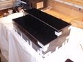
Battery Tray Construction
Overview
The next step is to start constructing the mechanical components which will be used in the conversion. The battery trays are where the new lead-acid (PbA) batteries will sit. The trays will then be mounted on rails in the trunk and a top will be placed over it to secure the batteries down. The battery trays are the same for both the classic and alternative mounting methods.
Approx. Time Requirement: 10-12 hours
Tools needed
- Metal Drill Bits: 3/32, 1/8, 5/32, 7/32
- Hacksaw with metal blade (or other method of cutting 1/8 inch aluminum)
- Drill or Dremel
- Drill or Dremel press recommended
- Metal file for filing rough edges.
- Wood saw
- Pop riveting tool
- Grinder (either an attachment for Dremel or bench grinder)
Parts needed
- Aluminum material
- Either 3/4" or 1" by 1/8" thick aluminum angle iron (2x 8 foot sections, 1x 4 foot section)
- 1/4" Aluminum channel iron (1x 8 foot section, 1x 4 foot section)
- 32 5/32 thick, 1/4 inch grip pop rivets
- 32 #4 flat head self threading screws at least 1/2 inch long
- Small piece of plywood for making jig (optional, but makes things easier.)
- Small pieces of wood for making jig (optional)
- Wood screws (optional)
Assembly Steps
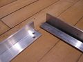
- Cut 4 sections of the 1/4" aluminum channel iron to the exact length of the batteries (should be 7 1/16 inches.) Having the batteries actually present is important for measuring. A total of 16 of these pieces will be required for all 4 trays.
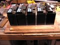
- Lay out 5 batteries and put the 1/4" aluminum channel irons between the batteries. Measure out the length and cut 2 sections of the aluminum angle irons to the length of the batteries (should be 16 5/16 inches.) A total of 8 of these sections will be required for all 4 trays. See photos below for how to layout the pack.
- Layout 5 batteries with the angle irons from above and measure the width and cut the 2 end pieces (should be 7 1/4 inches.) A total of 8 of these pieces will be required for all 4.
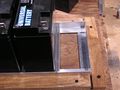
- Lay everything out on top of a piece of plywood and double check measurements with batteries set in the tray as shown below. It is important that the end pieces are under the pieces that run along the length of the tray.
- Screw down blocks of wood around outside of the frame as shown to hold the outside angle irons exactly where they are.
- Remove the batteries one by one and put in pieces of wood where the batteries were to hold frame and aluminum channel irons in place. This jig will hold all the pieces together while drilling.
- Using a small drill press or preferably a Dremel drill press, drill 2 3/32" holes into each corner (or probably only one if using 3/4" angle irons.)
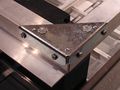
- Once the holes are drilled, remove the top angle iron (the 16 5/16 inch one) and using a 1/8" drill bit, widen the holes so that the #4 screws can pass through them freely (only do this on the longer angle iron, not the bottom!) Then counter-sink with a 7/32" drill bit so that the screw will sit flush in the aluminum (see photo below.)
- Put in #4 self threading screws. The screws should grab into the smaller angle iron and hold the angle irons together firmly. The screws will stick out the other side.
- Using a cutoff attachment on a Dremel (or a hacksaw, but Dremel works much better), cut the screws off. Then grind them down flat using the cut off attachment on a Dremel or a bench grinder.
- Re-insert the finished angle iron frame into jig, and place channel irons in place. Drill 5/32" holes at each end.
- Using a pop-riveting tool, insert 5/32" aluminum rivets into the channel irons from the bottom and tighten.
- Repeat 3 more times for a total of 4 trays.
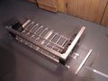
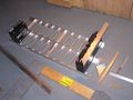
Photos
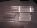
All necessary cut aluminum pieces for 4 trays
Tray set together with batteries
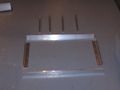
Tray parts laid out
Place wood around tray frame
Inserting wood blocks to hold aluminum
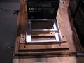
Inserting wood blocks to hold aluminum
Holes drilled in aluminum
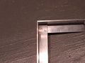
Finished corner with screws in
Shows the self threading screws sticking out
The finished tray
All 4 finished trays laid out like they will be


Battery Box Supports (Classic Method)
Approx. Time Requirement:
Overview
The battery box supports are what the battery trays will sit on. In the classic method, aluminum angle irons are bolted onto 2 steel tubes which are bolted to the trunk. If you have choosen the alternative method, skip this section and goto the next section.
Tools Needed
- Chopsaw with metal cutoff blade (hacksaw or jig saw will also work)
Parts Needed
- 1 1/2 inch by 1/8 inch thick aluminum angle iron (2x 8 foot sections)
- 1 1/2 inch by 1/8 inch thick aluminum strip (1x 4 foot section) (optional for extra strength)
- 2 3 foot long 1/2 inch or 3/4 inch steel tubes.
- Screws, Nuts, Lockwashers, Bolts
Assembly Steps
- Cut 4 aluminum angle irons 38 inches long and layout so that 2 trays sit into each pair (see photos) (Todo: Length may be slightly long, you will probably need to adjust the length when mounting!)
- Optionally cut the aluminum strip to the same length as the angle irons and set vertically in the middle of the assembly. This strip would then be bolted horizontally with the 2 center angle irons in the center and on each side. The idea is to reduce bounce in the center (weakest part) of the battery pack when going over bumps.
- Cut the steel tubes to the appropriate length (Todo Get exact length)
- Lay everything out as shown in the first photo and use the battery trays to determine the spacing. Leave enough space between the trays for a 1/4" nut.
- Mark the locations where the aluminum angles sit on the steel tube and drill holes.
- Drill holes in the opposite side of the steel tube, big enough to fit the head of a bolt through
- Drill 2 additional holes in each steel tube in the middle of where each tray will sit. Again, drill out the other side so a nut can be fit through it. Then put a threaded 5/8" threaded rod through the hole and put a nut on each side (and a lockwasher on one side.) This will serve as the holddown for the battery box top.
- Drill 4 holes through the tube, evenly spaced over the entire length. These holes are for mounting the battery box frame to the car.
- Drill additional holes as needed to support the electronics tray
- Once holes are all drilled, coat the steel tube with anti-rust paint / spraypaint.
Photos
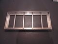
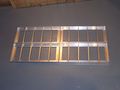
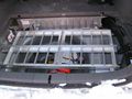
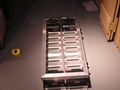
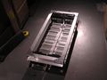
The completed battery box sitting on steel tubes (unattached)
Shows how the box sits on the aluminum angle supports. Also includes optional 1 1/2 inch aluminum strip in center.
During construction, shows supports without optional strip in center.


Battery Box Supports (Alternative Method)

Approx. Time Requirement: 4-7 hours
Overview
In the alternative mounting method, the battery trays sit on aluminum angle irons which either sit directly on the trunk or on rubber pads (which allow the use of battery heaters.) The battery box is supported by brackets attached to the OEM battery mouting screws and two steel angle irons bolted to the trunk. If you have choosen the classic mounting method, skip this section.
Tools Needed
- Chopsaw with metal cutoff blade (hacksaw or jig saw will also work)
- Bench grinder
Parts Needed
- 1 1/2 inch by 1/8 inch thick aluminum angle iron (2x 8 foot sections)
- 1 1/2 inch by 1/8 inch thick aluminum strip (1x 4 foot section) (optional for extra strength)
- 16 inches of steel 1 1/2 inch angle iron
- 2 joist hangers for electrical conduit
- Screws, Nuts, Lockwashers, Bolts
- 1/4" nuts
- 1/4" or 1/8" rubber pads (optional, but required if heating pads are to be installed.)
- anti-rust paint or spraypaint
Assembly Steps
The center strip
- See the diagram to the right to see how everything assembles.
- Cut 4 aluminum angle irons 38 inches long and layout so that 2 trays sit into each pair (see photos) (Todo: Length is too long, you will need to adjust the length when mounting, so be careful drilling holes, test fit first!)
- Optionally cut the aluminum strip to the same length as the angle irons and set vertically in the middle of the assembly (for strength). This strip would then be bolted horizontally with the 2 center angle irons in the center and on each side. The idea is to reduce bounce in the center (weakest part) of the battery pack when going over bumps.
- Lay out 2 aluminum angles so they form a "T" with the top of the "T" being on the floor. Optionaly insert the aluminum strip into the middle
- Lay everything out as shown in the first photo and use the battery trays to determine the spacing. Leave enough space between the trays in the middle for a 1/4" nut.
- Drill holes through each end of the assembly to anchor the two angles (and optionally the strip) together. The holes must be outside where the battery trays will sit (remember to leave space for a 1/4" nut (which is larger than 1/4")
- Optionally, cut rubber pads to go under each of the aluminum angles.
- Other holes will need to be drilled later when ready to mount.
Steel Angle Iron Brackets
- Cut 4 sections of steel angle iron about 1 to 1 1/2 inches long
- Drill a 3/8" hole in the center on one side of the angle iron.
- On the inside of the angle iron, weld (or use JB weld or another strong epoxy) a 5/8" nut on the inside so a bolt can go through the angle iron and into the nut
- Drill a 5/8" hole in the center of the other side of the angle iron
- Paint the steel with a clean metal anti-rust primer (then allow to dry)
- Spray or paint the primed steel with anti-rust paint
Steel Supports
- Cut 2 sections of steel angle iron about 4 inches long each
- Drill 2 5/8" holes in the bottom of the angle iron
- These will be used later for mounting into the Prius - the rest of the assembly must be done later
Todo This isn't finished - check the diagram for more details
Photos
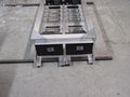
Shows how the box sits on the aluminum angle supports. Also includes optional 1 1/2 inch aluminum strip in center.
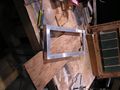
Test fitting in the Prius
Support Steel mounted
Shows the optional rubber pads
Detailed photo of the right side
Detailed photo of the left side
With the battery trays in


Battery Box Top
Approx. Time Requirement: 10 hours
Tools needed
- Metal Drill Bits:
- Chopsaw with metal cutoff blade very helpful (must be capable of 45 degree angles.)
- Tablesaw with Plexiglass blade, or other method of cutting Plexiglass
- Drill
- Metal file for filing rough edges.
- Dremmel
- Cutoff attachment for Dremmel
Parts Needed
- Aluminum material
- 1 1/2 inch by 1/8 thick aluminum angle iron (2x 8 foot sections)
- 1 inch by 1/8 inch thick aluminum angle iron (1x 4 foot sections for classic - 8 feet for the alternative mounting method)
- Corner brackets - can be found at Mennards in shelving hardware section
- 24x #8-32 flat head machine screws
- 16x #8-32 nuts
- 8x #8-32 x 1/4 inch binding posts
- 1/4 inch Plexiglass or (preferably) Lexan sheet, at least 33 inches by 18.5 inches.
- 4 small non-conductive nylon screw and binding posts (for holding Plexiglass "shields")
Assembly Steps
- Cut 2 strips of Plexiglass (or Lexan) 32.5 inches by 1.5 inches. These peices will act as a sheild between the battery terminals and the aluminum (to prevent shorts.)
- Cut opposing 45 degree angle at the end of 2 of the 1 1/2 inch aluminum angle iron peices to form one of the corners.
- Layout the four trays in the frame angle irons (important for getting correct measurements.)
- Place 4 batteries in the trays, one in each corner (see photo.)
- Place electrical tape over the terminals on the batteries to help prevent any arcs.
- Make sure to leave space for the middle bolt down and bolts for the frame. (The battery box base isn't finished yet and requires space in the middle.)
- Set one of the cut angle irons on top of the batteries (be sure not to arc the batteries!) Place the Plexiglass "Shield" in place and use clamps to it there. This allows for accurate measurements.
- Lay the other angle iron with the opposing 45 degree angle out and measure the width & cut with a 45 degree angle (end peice should be about 15 3/8 inches wide.)
- Hold the angle iron that will be used to bolt down the top to the end of the battery pack (use clamps to hold it on.) For the classic mounting method, this is only required on the left and right sides. For the alternative mouting method, the angles should go around the entire battery box top.
- Holding the angle irons and bolt down angle iron right where they should be, set the corner bracket on the corner and make sure that it covers the angle iron that will be used to bolt down the battery box.
- Mark where the holes on the top of the bracket are on the angle iron (or drill holes if necessary.)
- Using the Dremmel cutoff tool, cut down the binding post so that it does not stick all the way thought the bracket if set on top (see picture.)
- Drill a hole in the angle iron and countersink it so that the #8 flat top machine screw fits flush. Put screw in and repeate for the other angle iron.
- Repeate for other sides cutting the angle irons to the right lengths. The length of the angle iron on the side of the battery box should be 34 inches.
- To strengthen the structure of the top, drill holes in from the sides, countersink from the inside and bolt using #8 flat head screws and nuts (bolting the top down is important, remember that the top must hold weight if the car goes over large bumps or is involved in an accident or rollover.)
- Using a drill press or drill, drill through the Plexiglass on the side and the aluminum angle irons near the edges. Countersink the hole in the Plexiglass and insert non-conductive nylon screws and binding posts to hold Plexiglass in place.
- Using the Dremmel with cutoff attachment, grind off the bolts that are sticking out.
- Cut the Plexiglass sheet to the correct length and width to fit snuggly into the top of the battery box.
- Holes need to be drilled into the bolt down angle irons on each side, but I don't have those measurements and it depends how it is bolted down. Holes also need to be drilled in the middle on each aluminum angle iron to clamp down the top to the bottom of the battery box for extra strength.
Photos
Starting on the top of the battery box
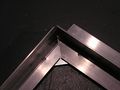
45 degree angles cut in angle irons
Corner bracket just set on the top
3 angle irons cut and just sitting on the box
Shows the Plexiglass "shield" on the inside of the angle irons
Partially assembled battery box - bolted on top, but not the sides
Inside of the corner of the battery box top
Binding posts that I choose to use. They worked, but they aren't part of the official conversion method
A completed corner, bolts in and have been ground off.
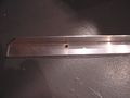
Shows the angle iron that will be used to bolt down the top
Mostly finished battery box. Still lacking the bolts in the center of the pack, holes for bolting the top down and holes in the frame


Tips
- If you are buying a new metal cutoff blade for an existing chopsaw, make sure to get one that is large enough to actually cut all the way through the metal with your specific chopsaw.
- Aluminum blades with small teeth do not seem to work well for cutting through 1/8 aluminum angle irons! They grab and tend to throw the saw and are almost impossible to control. Don't attempt an aluminum cutting blade with teeth on a radial saw!
- A hacksaw can work in place of the metal cutoff blade, however it is much more difficult to get straight cuts, even with a metal guide for the hacksaw.
- A jig saw seems to work well for cutting the aluminum angle irons
Control Board
There are presently 2 control board options. The Interim control board (also known as the Basic control board) and the CAN control board (still in the early stages, but available)
The Interim control board (a.k.a. basic control board) is used to drive contactors from CAN-View. With this setup, CAN-View is required and is the controlling computer, the Interim control board interprets the signals from CAN-View and drives the contactors. So if you have CAN-View, and you want to use it to control the conversion, this is the board you need. If you go the CAN control board route, neither of these are used. The Interim board costs around $14.50 for the board itself, and roughly $25 for components (or $65 pre-assembled.) The Interim board is available here: [1]. The DigiKey Quick order parts list for the Interim board is here: [2].
The CAN control board talks directly with the car over the CAN bus and also contains the circuitry to drive the contactors, so the board takes over what CAN-View used to be used for as well as takes over what the Interim control board does, so neither CAN-View nor the Interim control board are used in this setup. The CAN control board can do everything the CAN-View + Interim control board setup can do plus more (SOC spoofing, sense if the car is still plugged in when you stat it up, etc.) The CAN control board's software is open source and can easily be updated / customized with knowledge of C programming language and a PIC programmer.
In either case, however, CAN-View or ScanGuage are very valuable for telling what is going on behind the scenes of the car and making sure that everything is working properly and highly recommended.
LED Board

Approx. time requirement: 2 hours
This board is optional and can only be used with the Interim control board. The CAN control board takes the place of this board.
Tools Needed
- Soldering Iron
- Solder
Parts Needed
See the PriusPlus-PartsList page for the parts list.
Todo The schematics need to be updated to match new schematics.
Electronic/Electric Sub Part Construction
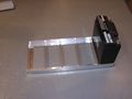
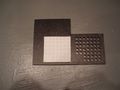
Diode
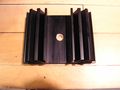
The diode must be firmly and correctly mounted to the heatsink. The diode has a 1/4" stud which passes through the heatsink but does not touch the heatsink. A shoulder or insulating nylon tube must be placed over the stud where the diode passes through the heatsink. This is important so the diode does not electrically make contact with the heatsink. Additionally, 2 electrically insulating, but thermally conductive pads (or mica) must be used on both sides of the heatsink to prevent the diode from making contact on either side of the heatsink. See photos below for how to mount the diode:
Photos

The DO-5 Diode as it arrives from DigiKey
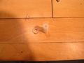
The nylon spacer shown next to what it was made from
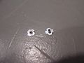
The heatsink with a hole drilled for the spacer
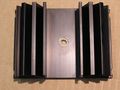
Nylon spacer inserted into the hole in the heatsink
Back side - Diode mounted on heatsink
Front side - Diode mounted on heatsink


Snubbers
Solder together one lead of the .47uF, 500V capacitor and one lead of the 22 ohm 1 watt resistor. Put heat shrink tubing around the other 2 leads and crimp on ring terminals and solder the crimps to the leads for a better connection. The snubbers are then placed across the two contactors.
Low Voltage Interconnects
A list of helpful Molex connector tools on DigiKey can be found here.
Todo
Electronics Tray (Classic Method)

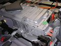
Todo This section needs to be expanded. please help us complete this section! Email chris at infolaunch.com to help Basically, take 1/4" ABS plastic, cut the bottom, back, sides. Cut holes in the fans on the sides, and use small shelving brackets to secure the pieces together. Attach electronic components with screws. Plexiglass top.
Todo The internal wiring should be detailed in this section. Please refer to the schematics on the RawData page for now.
The electronics tray

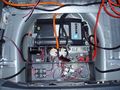
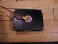
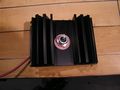
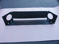
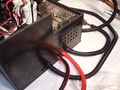
Electronics Box (Alternative)

Todo This section needs to be expanded please help us complete this section! Email chris at infolaunch.com to help. Basically, take 1/4" ABS plastic, cut a bottom, sides, back, front, middle divider, fan divider, and rear top. The front top is 1/4" plexiglass for easy viewing (or more ABS if preferred.) The fan divider is designed to be easily retractable for easy replacement without removing the battery box. Mount the fuse holders with 2 screws in the middle, the contactors, power supply, relays, etc. Preferably use very short self tapping screws that don't go through the plastic to provide electrical isolation from the rest of the car (optional.) It may be useful to use a Dremmel with a small drill bit to star the hole, use the self tapping screw to start the thread and then use a cutoff small screw. Otherwise, countersink a flat head screw on the outside of the box and use nuts and lock washers on the inside.
Todo The internal wiring should be detailed in this section. Please refer to the schematics on the RawData page for now.
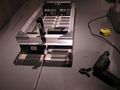
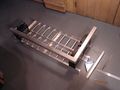
Starting with the materials
The electronics box taped together
Components being mounted
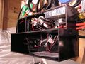
Partly populated electronics box
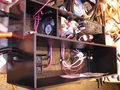
Partly populated electronics box
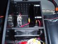
Close up of the diode
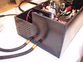
Left outside of electronics box
Right outside of the electronics box
Close up of the mounted contactors
Close up of the mounted fuses
The electronics box with the HV section's cover resting on top


Installation Into the Prius
Now that the sub components are built, it is time to start installing things into the Prius. The following sections will each attempt to leave the Prius in a drivable state after the section is completed.
Disassembling the Prius
Remove user-removable parts
Todo This needs to be finished Remove the false floor, the central storage bin, side storage bin and spare tire.
Battery Carpet & Seat Removal


Remove the two bolts holding down the carpeting over the OEM battery. Be sure to keep them in a plastic bag so they do not get lost. Then lift up on the Velcro attaching to the rear seats. Then, simply pull straight up on the carpeting assembly. It will snap out and expose the top of the OEM battery. There are 2 carpeting clips that must be removed to fully remove the cover from the OEM battery.
With the OEM battery carpeting removed (or the Velcro simply pulled up), remove the two bolts holding in the seat. The seat back then comes out giving access to the front side of the OEM battery (needed for the OEM tie-in.)
Side panel Removal
Both of the carpeted side panels in the rear of the Prius must be removed. The driver's side panel must be removed to access the OEM battery for tie-in, and the passenger's side must be removed to access the OEM battery fan to add the override wiring.
- Remove the screen from the trunk (if it hasn't been already.)
- Remove the cover from the driver's side storage cubby hole (if it hasn't been already.)
- Remove the black strip in the very rear of the trunk (where the latch is for the trunk) by simply lifting straight up (it will pop out.)
- Remove the arm rest sections on the outside of the seats (Todo - add photos)
- Remove the 10mm bolt inside the screen holder using a ratchet with an extension
- Remove the 10mm bolt in the back of the side panel in the section which holds the screen if were deployed. This can be done with a 10mm ratchet or a screwdriver.
- Pull straight out on the entire assembly.
- On the drivers side, there is a wire which connects to the trunk lamp which needs to be disconnected.
- Repeat instructions for the passenger's side.
Routing CAN-View cables to trunk
Todo This section needs to be improved.
Take off the kick panels on either the driver's side or passenger's side, insert CAN-View cable, ribbon cable (for LED board) and EV mode cable (1 wire) and route into trunk.
Air Vents (Classic Method)
Remove spare tire and the two black drain plugs that sit in the tire well. You may have to use a dremmel to open the hole so you can drop in the [Delete later-(Ron I think I found a piece of conduit that will flush mount in here. The PVC pipe can be glued to it. I’ll get you a part number and picture. By doing this a project could be prepped weeks in advance and the spare will still fit in there until the final conversion days.) ] 2” PVC threaded coupling. Next connect the 2” 90 deg. Elbow and then a length of 2” PVC pipe per this photo (add photo showing underside of car with both pipes pointing back to the rear.)
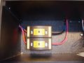
Installing the Outlet Box (Classic Method)
Todo This section needs to be expanded. Please help us finish this section! Write chris at infolaunch.com to help and for the 120 volt wiring schematics that need to be posted here.
Take a standard plastic wall 4 gang outlet box, route a 12/3 cable into the box (with strain relief), and wire one duplex (2 individual outlets) directly to the incoming power. Then wire one outlet of the other duplex through one relay, and the other through the second relay (such that the outlets are on only when the relays are on.) The 2 individual outlets controlled by relays are designed for heating pads for the OEM battery and the PHEV battery pack. The other 2, always on when plugged in outlets are designed to power the charger and the power supply.
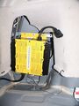
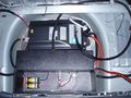
Install Charger / Electronics Box (Alternative Method)
Todo This section needs to be expanded.
Todo Add relevant photos from RawData page
Take a sheet of zinc coated steel and cut it out so that it fits neatly in the bottom of the tire well. Drill a hole in the center where the spare tire screw goes (used to hold the sheet in place.) Then, place the charger in the back, behind the center hole. It may be necessary to use pipe or washers to offset the charger from the steel sheet an inch or so to get it to fit (depends on charger used.) Drill holes through the steel sheet and mount charger to it. Then, put a thin carpet or sturdy insulation on the underside of the steel sheet to prevent rattling while driving. It may be necessary to use a 3/4" small block of wood with a hole through the middle to offset the center of the steel where the screw goes into the tire well mount to keep the steel from bending / rattling while driving. The screw is metric. Then, using several strips of extra strength velcro, velcro the bottom of the electronics box to the steel sheet.
Install Batt. Box Foundation / Electronics Tray (Classic Method)
Line up the battery box support steel tubes where they should go and drill holes into the trunk floor. It may be necessary to remove part or all of the heat shielding from the muffler on the underside of the car to find the holes. Bolt down.
(Todo Need to detail removing the heat shield on the underside of the car.) To remove the plastic shield on the driver's side rear of the car, use a flat screw driver to pop out the 3 fasteners. On the back of the shield there is a 10mm bolt holding the plastic shield in place which also needs to be removed.
Install Battery Box Foundation (Alternative Method)
Todo This needs to be better documented
Remove the two bolts holding down the OEM battery in that stick out into the tire well. Mount the modified I beam brackets so that the back with the screw hole is facing directly towards the back of the car. Drill a hole in the rear support aluminum angle iron to match with those screw holes, countersink a flat screw into that. (see diagram and photos for details on how everything goes together.) On the driver's side, drill a hole through the aluminum for the post on the SKS sensor. The middle section just sits on the steel floor, though bolts into the Prius body may be a good idea. (its held in primarily by the battery box top, but extra strength in the event of a crash would be good.) The rear piece needs to have holes drilled in the Prius steel floor and the steel angle irons (see diagram) bolted to either the steel floor or to the frame member below them off to the side a bit. If bolting to the steel floor, a steel strip on the opposite side should be used, and at least 2 bolts should be used for added strength.
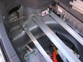
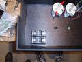
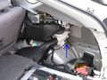
OEM Battery Fan Control Tap

Todo Upload new version of schematic
Taps must be added to force the OEM fan on at lower temperatures so the car can remain in EV mode.
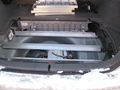
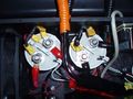
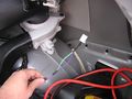
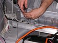
The tapping is done at the OEM battery fan. You reach it by taking the right rear inner body panel off (instructions in the Toyota service manual), reaching up inside the ducting, above the right rear wheelwell, and unplugging the power plug to the fan. The plug is not visible; you must unplug it (and plug it in again) by feel. The plug has two light green wires attached to one pin, and two violet wires attached to the other.
Use #18 or larger wires for all of the following. All three wires are run down to the control board, then the OEM battery plug is plugged back into the fan.
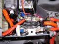
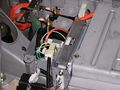
Alternative 1: Attach a green wire to one or both of the light green wires, e.g. via a red clip-on wire splice (make sure it makes solid contact). Then cut both of the violet wires about 2" from the OEM battery fan plug. Splice a violet wire onto both of the violet wires that were cut off, and a black wire to one or both of the violet wires still attached to the plug. Splice all three (1N5402, 1N5403, or 1N5404) 3A diodes in parallel as shown, between the violet and black wires near the fan plug, with the cathode (the end with the band) connected to the violet wire. For proper heat dissipation, make sure that the leads and all connections are well insulated, that the body of each diode is open to air flow, and that the diodes are not pressed against each other, and that the whole assembly, when the plug is plugged in, is solidly suspended in mid-air. Three 3A diodes are used in parallel for a maximum of 5A because heat dissipation may be compromised even when installed as above. The other end of all three wires are routed to the control board, where they are attached to J8F as per the diagram.
The unmodified wiring
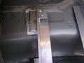
Unplugged and rubber casing stripped back
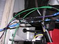
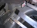
Ladder of diodes
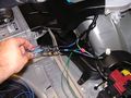
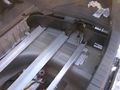
Finished wiring modification


Alternative 2 (does not cut Prius wires, but is expensive): Buy two each of the following Toyota replacement OEM battery plug and mating pins:
   OEM battery fan plug pins:  Toyota P/N 82998-12380
   OEM battery fan plug mating pins:  Toyota P/N 82998-12370
Splice one plug pin, a mating pin, and a green wire together. Splice a black wire to a plug pin, and a violet wire to a mating pin. Splice the three 1N5402 diodes between the violet and black wires as described above. Now remove the pin with the light green wires from the OEM battery fan plug, connect it to the mating pin with the green wire attached, and secure with heat-shrink tubing. Insert the plug pin attached to the green wire into the OEM battery fan plug. Next, remove the pin with the violet wires from the OEM battery plug and connect it to the mating pin with the violet wire attached, again securing it with heat-shrink tubing. Insert the plug pin attached to the black wire into the OEM battery fan plug. The pins are removed one at a time so that there is no possibility of getting them reversed when inserting the new pins. As above, the other end of all three wires are routed to the control board, where they are attached to J8F as per the diagram.
The pins can be removed from the OEM battery fan plug by inserting a tiny screwdriver from the back to push the plastic catch aside while pulling on the wire attached to the pin.
Safety Warning & Tips
Batteries can be dangerous and can cause serious injury or death and should only be worked on by persons qualified to do so. Both energy hazards from arcs (shorts) and electrical shock can cause serious injury or be fatal with a battery pack of this size. Battery packs are always live and cannot be shut off! The following are safety tips to help prevent arcs and shocks, but they are only tips and should not be taken as a go-ahead to perform work on battery packs. Extreme caution must be taken as it is very easy to accidentally set something on the battery without thinking or drop something and cause a shock or arc. Hire a qualified electrician to help for this part if there is any doubt.
- Remove all jewelry, especially gold, before working with batteries.
- Do not allow metal to come into contact with the batteries that could cause an arc (best practice is to not allow any metal near the battery at all.
- Use only fully insulated tools around batteries, especially in tight spaces (available in the electrical department in most hardware stores.)
- When wiring batteries, be sure the other end of the wire will not accidentally come into contact with any other part of the battery or metal frames. Taping or otherwise protecting the ends of wires is recommended.
- Wear rated rubber electricians gloves and outer protective gloves. Electricians gloves are not fail-proof and every effort should be made to only touch insulated tools even when wearing gloves.
- If electrician gloves aren't used, only one hand should be used so that a shock will not pass current through the heart.
- Always wear gloves when working on batteries (preferably rubber.)
- Install the jumpers in 48 volt sections and then connect those smaller sections together at the very end. This way voltages higher than 48 volts are only handled when installing 4 jumpers instead of 16.
- Even though the batteries are sealed, it is still possible for them to leak and splatter acid, especially if they are just charged, heated or an arc occurs. If a leak occurs, use baking soda to neutralize the acid and properly dispose. Eye protection is a good idea.
- Orient batteries in the tray to avoid terminal contact with any bolts or any metal pieces.
Tapping into OEM Battery
| General Disclaimer: (HV) (DC) injury or death hazard, use at your own risk, may void warranty. |
|---|
|
HV (High Voltage) DC (Direct Current) Warning: Traction Battery Packs, Motors, Chargers, and other HV sources could cause serious injury or death if proper precautions are not taken while working on or around such High Voltage Direct Current sources. Use this information at your own risk: There is no warranty expressed nor implied and we are not liable for any of your past, present, nor future actions. Even should you perform these modifications to the letter you could still damage any number of components in your vehicle causing it to no longer function. Even if it appears to function properly your actions may cause it to self destruct with collateral damage to surrounding properties other than your vehicle. By utilizing these ideas and instructions in an attempting to enhance national security, reduce gas consumption, vehicle "emissions", your carbon footprint, or smog, you do so at your own risk & peril. Warranty: In performing some of these modifications you may void your warranty with the vehicles manufacturer. See also our My wiki:General disclaimer |
This step MUST be performed by someone qualified to work on high voltage systems. Rated rubber electricians gloves should be used for working on the inside of the battery. Please fully read the Safety section before before attempting anything. Lethal voltages are present. Hire a qualified professional for this portion.
Todo: This section is not finished
Tools needed
- Voltmeter (capable of at least 300 volts DC)
- Ratchet
Parts needed
- 3 #6 AWG ring terminal crimps (an extra is good)
- 2 #8 AWG ring terminal crimps (extras are good)
- small 1 foot section of 6 AWG wire (with insulation rated 600v or higher, preferably THHN)
- non-conductive rubber cap
- electrical tape
- several feet of #8 AWG wire with insulation rated 600v or higher
- optional: 3/8" flex tubing
- optional: other flexible conduit
- Before attempting to open the OEM battery, the orange service disconnect MUST be fully removed from the OEM battery. To do this, lift up on the orange ring. Once it pops up, push the top part out, away from the battery. This will remove the service disconnect from the battery. Do not re-install the service disconnect until the OEM battery has been closed up. BE AWARE, THERE ARE STILL HIGH, LETHAL VOLTAGES INSIDE THE BATTERY EVEN THOUGH THE DISCONNECT HAS BEEN REMOVED!
- Take off the support holding the OEM battery in place. The bolts are found on the driver's side wheel well, on the OEM battery and behind the driver's side rear seat top (the seat top must be removed, see above for information on removing the seat back.)
- Carefully remove the bolts holding the cover on the driver's side of the OEM battery. The 2 bolts will need to be removed from where the orange cables come out of the battery to remove the cover. DO NOT TOUCH ANYTHING INSIDE
- Once opened, just beyond where the two orange wires enter the OEM battery there are 2 contactors with 2 white plastic shields on top. NEVER TOUCH THE TWO TERMINALS AT THE SAME TIME Using rated, insulated electrician's rubber gloves remove one of the white plastic pieces by lifting straight up. Using a voltmeter, test the DC voltage between the contactor terminal and ground. If voltage is present (often > 100 volts DC) keep the multimeter on the terminal until the voltage decreases to below 1 volt. After that has been done on one, remove the other white plastic piece and repeat for the other side. Then check the voltage between all of the contactor terminals (all 4) to ensure they are zero. This step must be repeated any time the orange service plug has been inserted into the battery to ensure safety.
- Disconnect the negative wire coming from the OEM battery from the contactor. It is the one fed through the hall effect sensor (see photo.) The wire must be removed from the hall effect sensor.
- Take the piece of 6AWG wire with a 6AWG ring connector firmly attached at both ends and feed it through the hall effect sensor and connect it to the contactor where you just removed the OEM negative battery wire. It is very important that this is tight and makes good contact.
- Feed in the new #8 AWG wire from the electronics tray through the opening where the 2 orange wires come through. Attach a #8 AWG ring connector to the wire. It is very important that this is tight and makes good contact.
- Bolt the #6 wire from the negative contactor, the negative wire from the OEM battery and the negative #8 AWG (black) wire from the electronics tray together as shown using a lockwasher (see photo.) It is very important that this is tight and makes good contact.
- Then wrap tightly with electrical tape (preferably orange), so that the entire assembly is covered with several layers of tape.
- Place a rubber cap on the top and wrap the rubber assembly in tape and attach firmly to the rest of the wire.
- Next, crimp on a #8 AWG ring terminal to the #8 Red wire coming from the electronics tray.
- Remove the bolt on the positive contactor's terminal and add the #8 AWG wire as shown (see photo.) It is very important that this is tight and makes good contact.
- Replace the white insulators that came off the top of the contactors
- Route the wire in the same way as the black wire out area where the 2 orange wires run
- Make sure there is a little slack wire inside the OEM battery. Then, optionally wrap the 3/8" flex tubing around the 2 new wires to the electronics tray and wrap them in orange electrical tape (orange is keeping in standard for high voltage wiring in hybrids.)
- Before reconnecting anything, be absolutely sure that the other end of the high voltage wires are fully insulated (i.e., make sure the Anderson PP75 connectors are on and that there is electrical tape preventing them from accidentally contacting any metal.
- Tap a yellow #22 or larger wire onto the yellow low voltage wire going to one of the contactors and route to the electronics tray or box.
Todo Add a photo of the yellow READY wire.
The OEM battery with the support bracket removed
Removing the OEM battery lid
After the OEM battery tie in is done
Shows the 2 white insulators on the contactors


Tap into the 12v Accessory Battery
Run 4 18 AWG wires (2 red, 2 black) from the electronics tray or box to the 12 volt accessory battery (located under the passenger side cubby hole. The 2 red wires should run into a 15 amp 32volt automotive fuse. The other side of the fuse should go to the 12v accessory battery. The black wire should either goto the black terminal on the battery or the chassis (but it must be a very clean connection to the chassis.) The other side of the wires goes to the control board through a .156" Molex KK connector.
Reassemble the Prius Trunk
Todo Needs to be written
Connecting the PbA batteries
Todo Much work needed yet
Parts Needed
- Qty 50 8 AWG crimp on ring terminals (probably wise to get a few extra!)
- 8 AWG wire (list total length used here.)
- Orange electrical tape
- 20x BB Battery EVP20-12B 12volt 20ah SLA AGM batteries (2 spares recommended.)
Assembly Steps
| General Disclaimer: (HV) (DC) injury or death hazard, use at your own risk, may void warranty. |
|---|
|
HV (High Voltage) DC (Direct Current) Warning: Traction Battery Packs, Motors, Chargers, and other HV sources could cause serious injury or death if proper precautions are not taken while working on or around such High Voltage Direct Current sources. Use this information at your own risk: There is no warranty expressed nor implied and we are not liable for any of your past, present, nor future actions. Even should you perform these modifications to the letter you could still damage any number of components in your vehicle causing it to no longer function. Even if it appears to function properly your actions may cause it to self destruct with collateral damage to surrounding properties other than your vehicle. By utilizing these ideas and instructions in an attempting to enhance national security, reduce gas consumption, vehicle "emissions", your carbon footprint, or smog, you do so at your own risk & peril. Warranty: In performing some of these modifications you may void your warranty with the vehicles manufacturer. See also our My wiki:General disclaimer |
Warning: Get an electrician or qualified person to do this, this is working with high voltages which can be lethal or start fires if not taken seriously.
Place trays in the foundation and the batteries in trays (look at photos on RawData page to see sequence.) Using crimp on ring terminals, make lengths of wire long enough to connect batteries and crimp the ring terminals on well. Make sure the crimps are very tight and make good contact. This is very important because they could otherwise heat up extremely hot and melt or start a fire. The batteries are arranged electrically into 4 60v sections. The front section and rear section are separated by one of the 60 amp 300v fuses (see HV schematics.) Each other section is separated by Anderson PP75 connectors for easy disconnect. Sections should be assembled individually to prevent voltages from being more than 60 volts until everything is ready to be connected and assembled. Leave the fuses disconnected until everything is finished. Then put on the battery box top and bolt it down.
Optional Bumper Mounted Inlet
This is an optional replacement for the mounted cord reel. There may be other inlets available, but a Marinco 150CCI works well and costs about $25-$30.
- Remove the plastic shield on the driver's side of the car if it hasn't been already (see above for instructions.)
- Using a circular drill bit with starting drill bit, drill a 1 7/8" hole in the bumper where you want the inlet to be mounted.
- Route the cable to the inlet before installing the inlet.
- Fasten the inlet to the bumper
Optional Mounted Cord Reel (Classic Method)
Todo Needs to be written by someone who knows how to do this.
The First Tests
Todo This needs much more work
First, using a voltmeter check to make sure that voltages are present both from the OEM battery (should be 220v or so) and from the PHEV pack (should be around 260v.) Plug the car into a ground faulted (preferably also arc faulted) outlet and check to see if the car starts to charge the PHEV battery.
Power up the car very briefly and check to see if the control board turns on. With CAN-View in ORIG mode (not PHEV), make sure that HVRL1 and HVRL2 are both off. Some LEDs should be on on the LED board.
Programming CAN-View/Control Board
Todo Polish this description and format nicely like Ryan's PiPrius ones.
Set the dip switches on the control board:
    DIPSW1:  1=OFF, 2=OFF, 3=ON, 4=ON, 5=ON   [ HVRL1 = RL3 OR RL5 OR RL6 ]  (RL2 will be reserved to force the OEM battery fan ON)
    DIPSW1:  6-10=OFF   (these would be used to control the optional current-limiting power resistor)
    DIPSW2:  1-5=OFF   (later, 2=ON will force the OEM battery fan ON when RL2 is ON)
    DIPSW2:  6-10=OFF   (these would be used to control a "Future use #1" output)
RL2 [settings don't yet matter]
For highway driving:
    RL3  ON <  71  OFF >  73 %SC   (%SOC)
    AND  ON   25  OFF <  30 Acl   (Amps DCL)
         ON >  45  OFF <  40 MPH
         ON < 100  OFF > 125 MPH   (never turns OFF)
               3 seconds to change
    Must be EV mode? NO
To stay in EV mode during acceleration:
    RL5  ON < 200  OFF > 235V
    AND  ON < 100  OFF > 125 MPH   (never turns OFF)
         ON < 100  OFF > 125 MPH   (never turns OFF)
         ON < 100  OFF > 125 MPH   (never turns OFF)
               0 seconds to change
    Must be EV mode? YES
For low speeds, to promote EV mode driving:
    RL6  ON <  61  OFF >  63 %SC   (%SOC)
    AND  ON < 100  OFF > 125 MPH   (never turns OFF)
         ON < 100  OFF > 125 MPH   (never turns OFF)
         ON < 100  OFF > 125 MPH   (never turns OFF)
               0 seconds to change
    Must be EV mode? NO
| General Disclaimer: (HV) (DC) injury or death hazard, use at your own risk, may void warranty. |
|---|
|
HV (High Voltage) DC (Direct Current) Warning: Traction Battery Packs, Motors, Chargers, and other HV sources could cause serious injury or death if proper precautions are not taken while working on or around such High Voltage Direct Current sources. Use this information at your own risk: There is no warranty expressed nor implied and we are not liable for any of your past, present, nor future actions. Even should you perform these modifications to the letter you could still damage any number of components in your vehicle causing it to no longer function. Even if it appears to function properly your actions may cause it to self destruct with collateral damage to surrounding properties other than your vehicle. By utilizing these ideas and instructions in an attempting to enhance national security, reduce gas consumption, vehicle "emissions", your carbon footprint, or smog, you do so at your own risk & peril. Warranty: In performing some of these modifications you may void your warranty with the vehicles manufacturer. See also our My wiki:General disclaimer |