|
General Disclaimer: (HV) (DC) injury or death hazard, use at your own risk, may void warranty. |
Difference between revisions of "Escape PHEV TechInfo"
DavideAndrea (talk | contribs) (→Photos: Changed title, added description) |
DavideAndrea (talk | contribs) |
||
| Line 37: | Line 37: | ||
| − | + | ===Traction battery general description=== | |
| + | |||
| + | ====Component locations==== | ||
| + | The battery includes (as seen when in the vehicle): | ||
| + | *Air blowers in the rear compartment | ||
| + | *NiMH cells in the center | ||
| + | **2 layers of cells | ||
| + | **each layer in a left and right group | ||
| + | **each group has 13 columns of 5 cells in series | ||
| + | **total: 2 * 2 * 13 * 5 = 260 cells | ||
| + | **pack voltage: 1.3 V * 260 = 338 V | ||
| + | *controller on the right side | ||
| + | *contactors and HV connector on the right-front corner | ||
| + | *safety plug on the left-right corner | ||
| + | *a converter of some sort on the left side | ||
| + | |||
<gallery> | <gallery> | ||
Image:batterypack-open1.jpg|Battery pack opened, rear view | Image:batterypack-open1.jpg|Battery pack opened, rear view | ||
| Line 44: | Line 59: | ||
Image:batterypack-power-conn.jpg|Battery pack power connector | Image:batterypack-power-conn.jpg|Battery pack power connector | ||
</gallery> | </gallery> | ||
| + | |||
| + | ====Connectors==== | ||
| + | [[Image:battery_iface.gif|thumb||right|Diagram of battery interface]] | ||
| + | The battery has 3 connectors, with a total of 34 wires: | ||
| + | * C4227A - 28 wires - control | ||
| + | * C4227B - 2 wires - low power HV to the AC/DC converter | ||
| + | * C4227C - 4 wires - traction HV, interlock signals | ||
===CAN bus=== | ===CAN bus=== | ||
Revision as of 01:12, 20 December 2006
Contents
Technical information on the Ford Escape useful when designing a Escape PHEV conversion.
2006 Year model
2007 Year model
Traction battery
Functions
Battery voltage
Cabling to traction battery
Traction Battery removal


From the hatch opening:
- Remove the carpet in the hatch compartment floor, to reveal the battery
- Turn the orange safety plug from LOCK to UNLOCK and pull it out
- Remove the black plastic air coupling on the rear-left
- Remove the bolts on either side of the battery (3 bolts on each side)
- Disconnect the battery:
- Orange HV connector on the right (flip the lever)
- Big black signal connector on the left (unscrews)
- Small connector next to the signal connector (snaps)
- Hook an engine hoist to the two round holes in the black metal on either side of the battery
- Hoist the battery out of the car
To open the battery:
- You need a #35 security Torx driver, and a #35 Torx driver
- Remove all the screws in the 2 top covers
- Cover over the fans
- Cover over the batteries and electronics
Traction battery general description
Component locations
The battery includes (as seen when in the vehicle):
- Air blowers in the rear compartment
- NiMH cells in the center
- 2 layers of cells
- each layer in a left and right group
- each group has 13 columns of 5 cells in series
- total: 2 * 2 * 13 * 5 = 260 cells
- pack voltage: 1.3 V * 260 = 338 V
- controller on the right side
- contactors and HV connector on the right-front corner
- safety plug on the left-right corner
- a converter of some sort on the left side
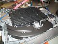
Battery pack opened, rear view
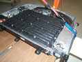
Battery pack opened, front view
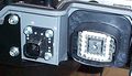
Battery pack data connector
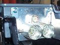
Battery pack power connector


Connectors
The battery has 3 connectors, with a total of 34 wires:
- C4227A - 28 wires - control
- C4227B - 2 wires - low power HV to the AC/DC converter
- C4227C - 4 wires - traction HV, interlock signals
CAN bus
If the conversion will replace the stock Battery ECU, it must talk directly with the vehicle CAN bus.
- Kvaser has a simple explanation of the CAN bus.
- wikipedia article on the CAN bus
CAN bus protocol
Battery ECU messages
Fault codes
| General Disclaimer: (HV) (DC) injury or death hazard, use at your own risk, may void warranty. |
|---|
|
HV (High Voltage) DC (Direct Current) Warning: Traction Battery Packs, Motors, Chargers, and other HV sources could cause serious injury or death if proper precautions are not taken while working on or around such High Voltage Direct Current sources. Use this information at your own risk: There is no warranty expressed nor implied and we are not liable for any of your past, present, nor future actions. Even should you perform these modifications to the letter you could still damage any number of components in your vehicle causing it to no longer function. Even if it appears to function properly your actions may cause it to self destruct with collateral damage to surrounding properties other than your vehicle. By utilizing these ideas and instructions in an attempting to enhance national security, reduce gas consumption, vehicle "emissions", your carbon footprint, or smog, you do so at your own risk & peril. Warranty: In performing some of these modifications you may void your warranty with the vehicles manufacturer. See also our My wiki:General disclaimer |