|
General Disclaimer: (HV) (DC) injury or death hazard, use at your own risk, may void warranty. |
Uploads by Cewert
Jump to navigation
Jump to search
This special page shows all uploaded files.
| Date | Name | Thumbnail | Size | Description | Versions |
|---|---|---|---|---|---|
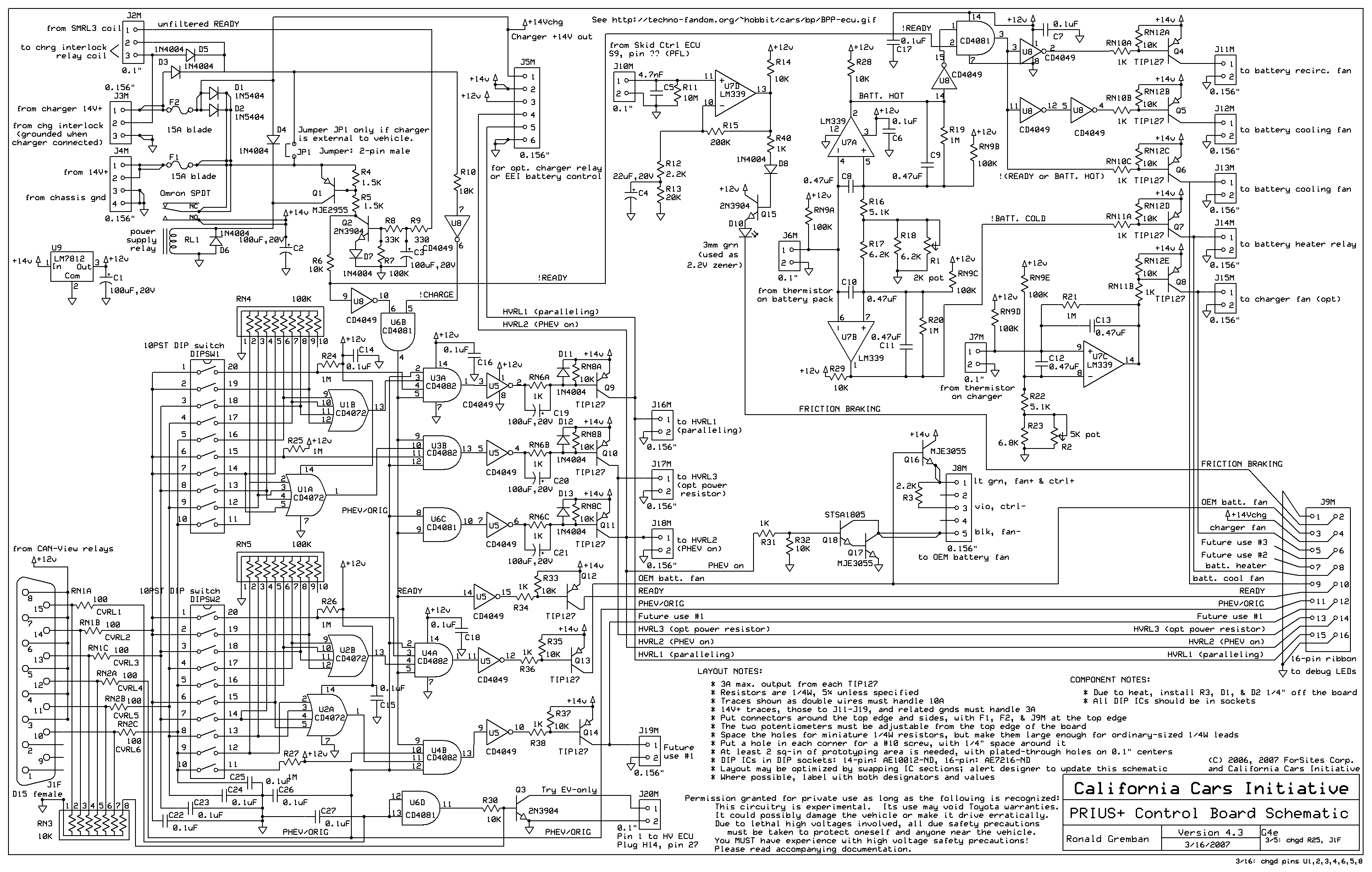
| 20:23, 15 April 2007 | EAA-PHEV-PRIUS-ControlBdSchematic.png (file) |  |
137 KB | v4.3_070316 | 7 |
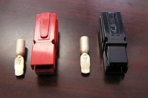
| 22:25, 28 March 2007 | PP75 Connectors.jpg (file) |  |
30 KB | PowerPole 75 amp connector housings and 8AWG crimps | 1 |
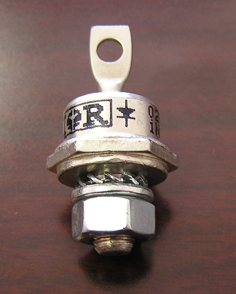
| 22:25, 28 March 2007 | DO-5 Diode.jpg (file) |  |
112 KB | The DO-5 Diode as it comes from DigiKey | 1 |
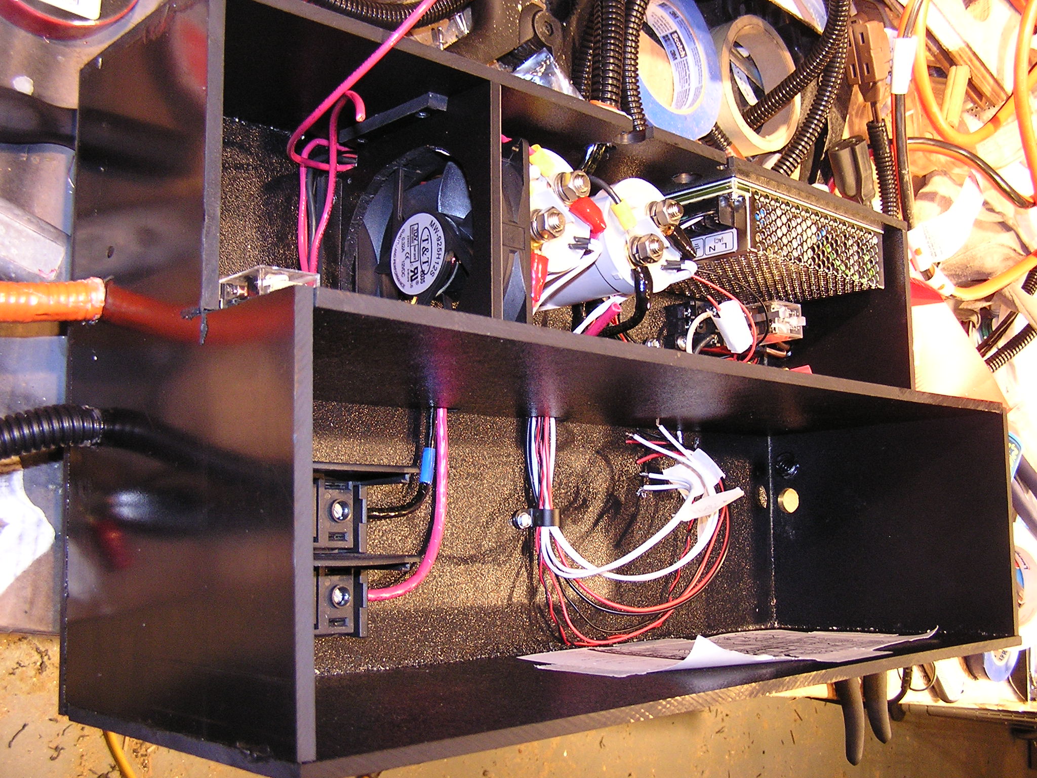
| 15:25, 21 March 2007 | Electronics Box Partial 2.jpg (file) |  |
717 KB | Partially completed electronics box for alt. mounting method. | 1 |
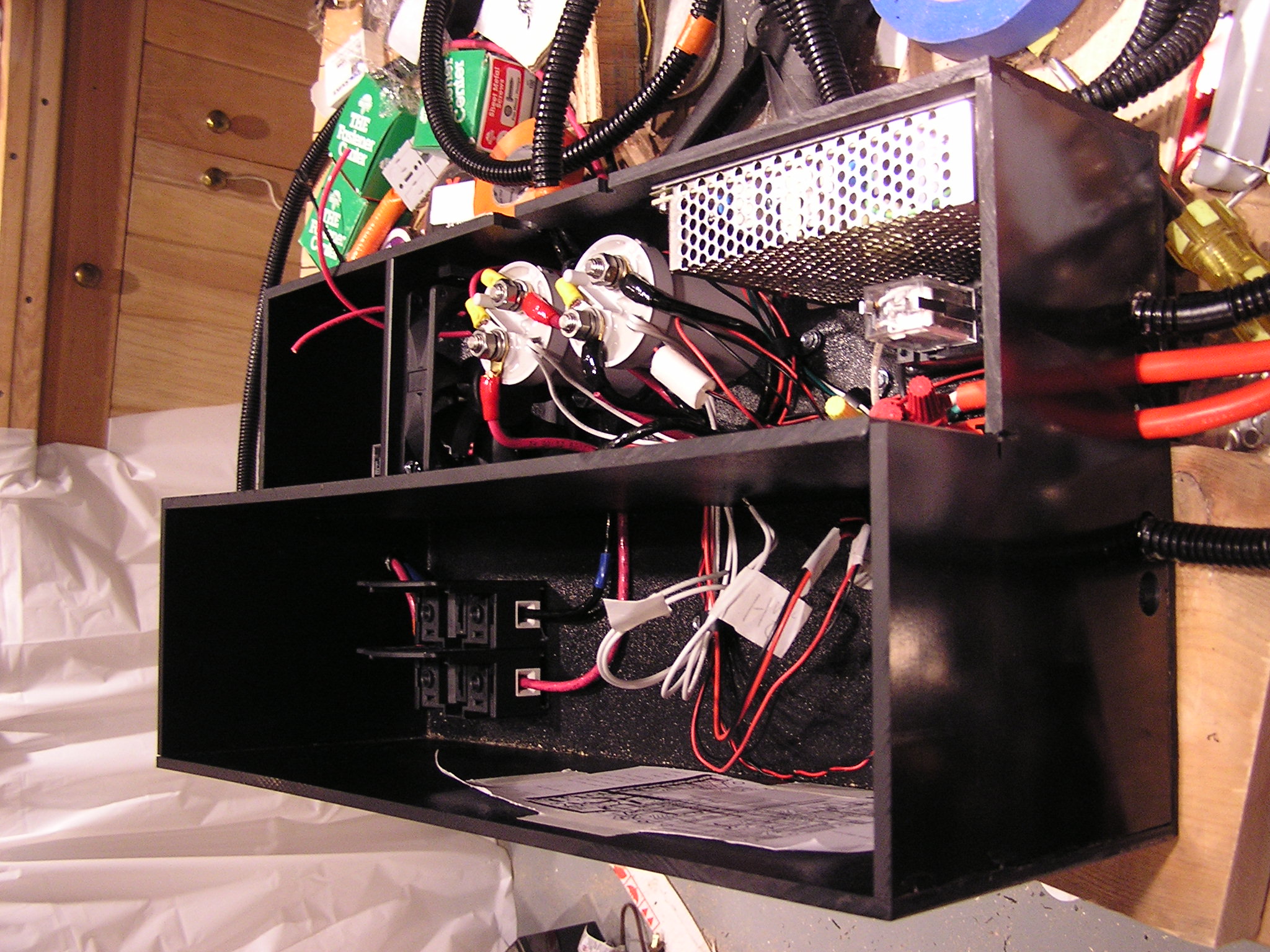
| 15:23, 21 March 2007 | Electronics Box Partial 1.jpg (file) |  |
679 KB | Mostly completed electronics box without top. This is for the alt. mounting method. | 1 |
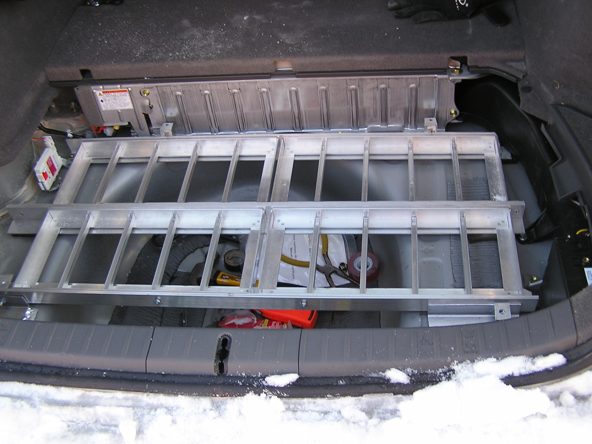
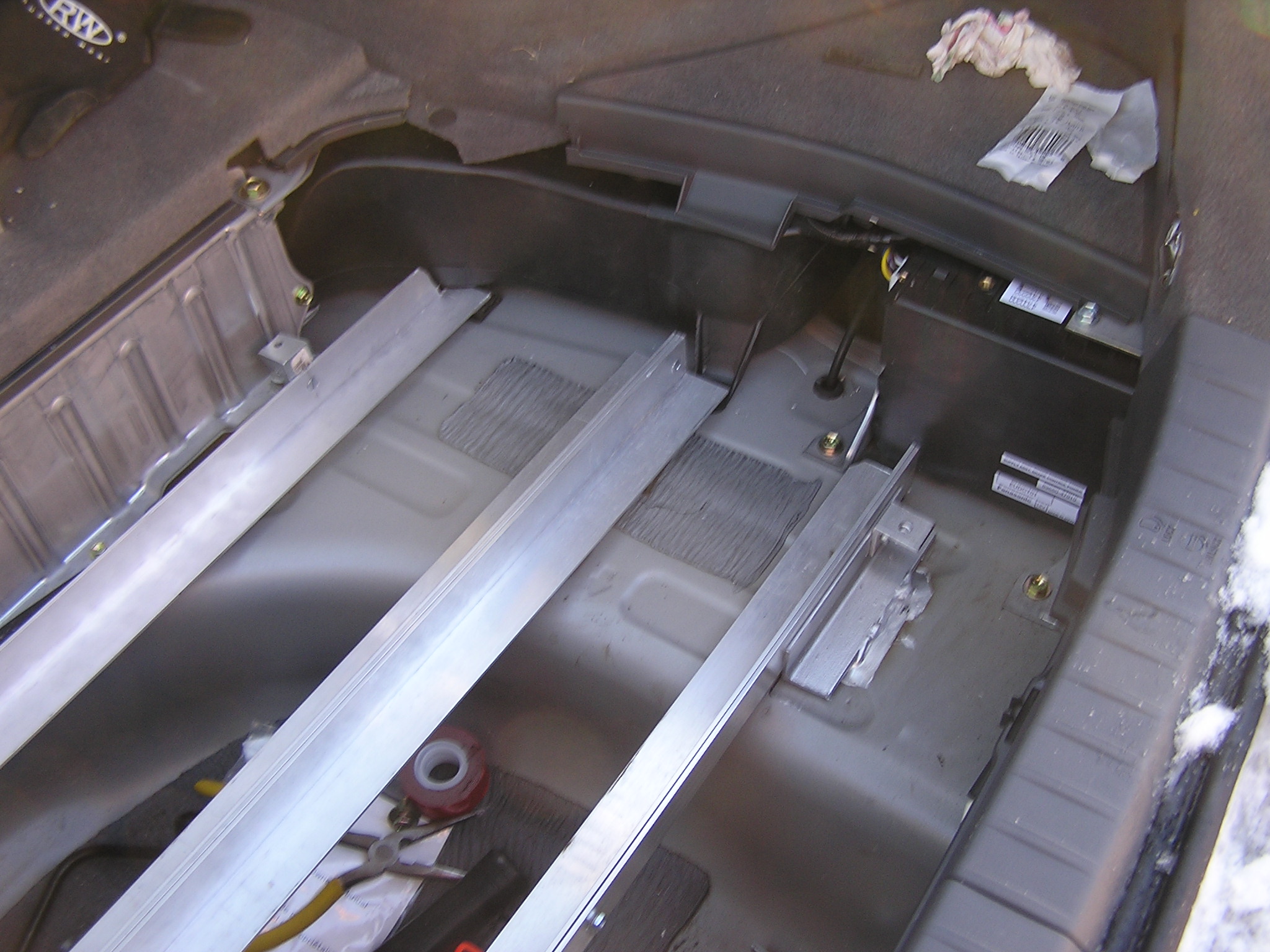
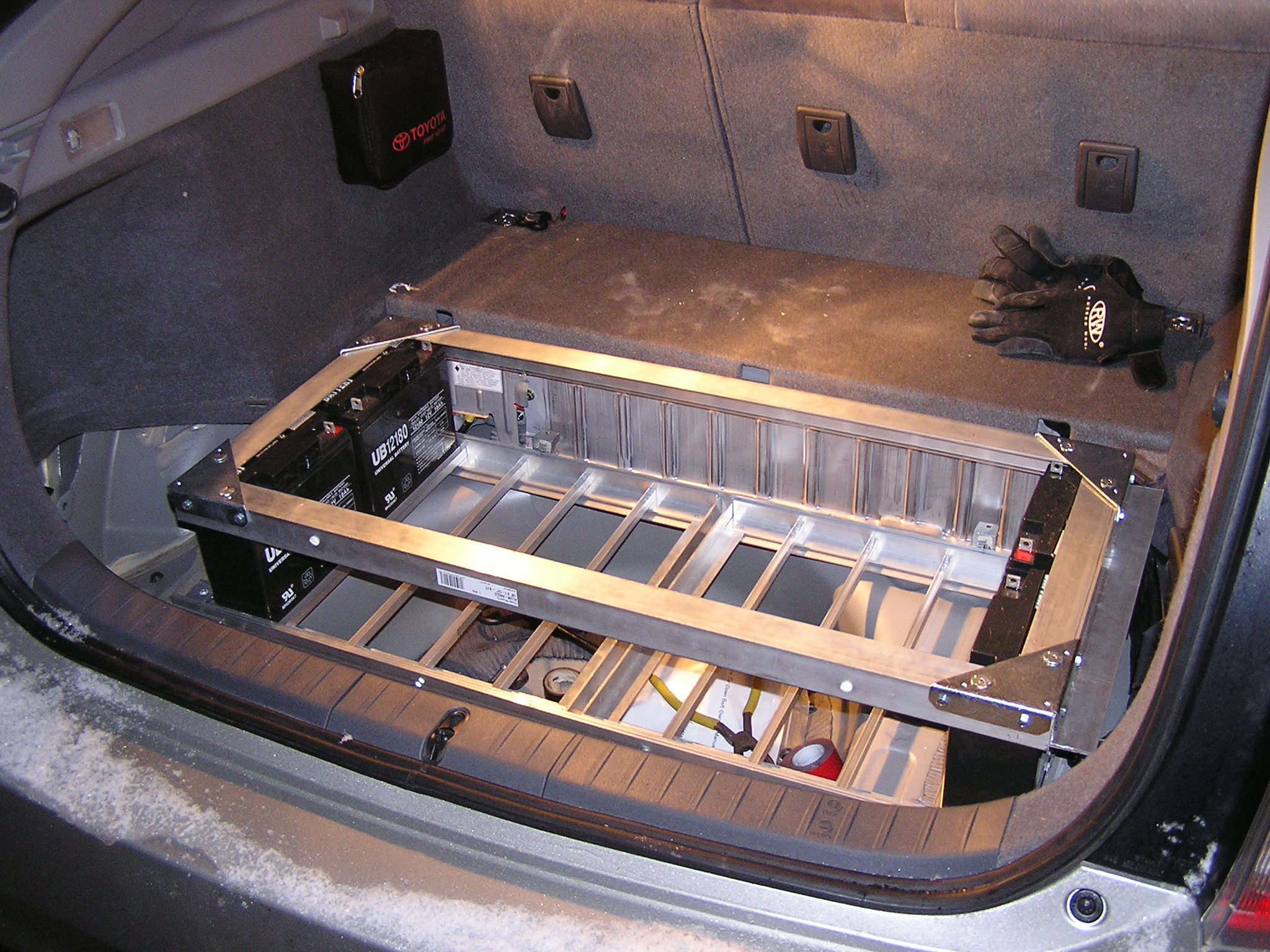
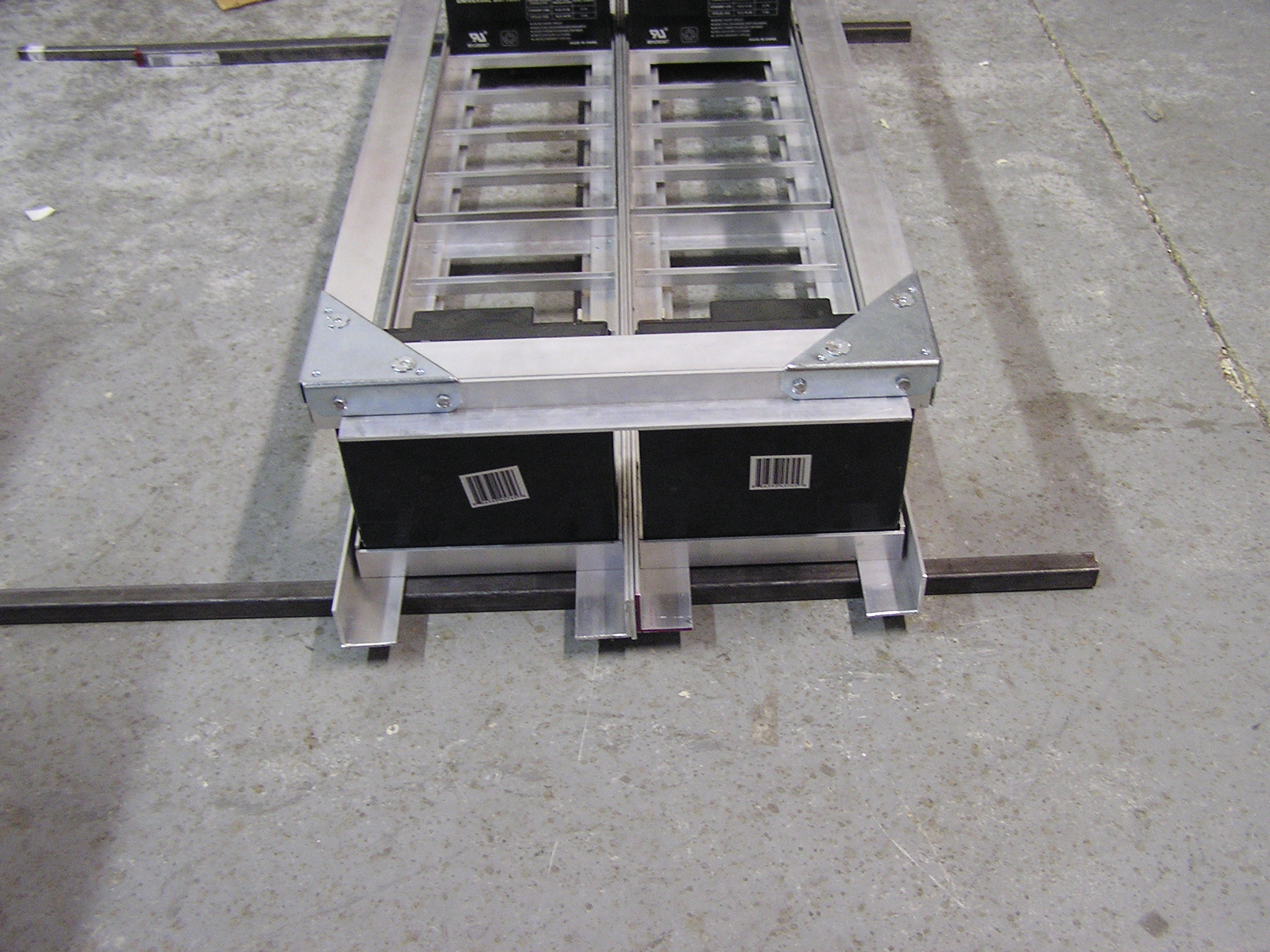
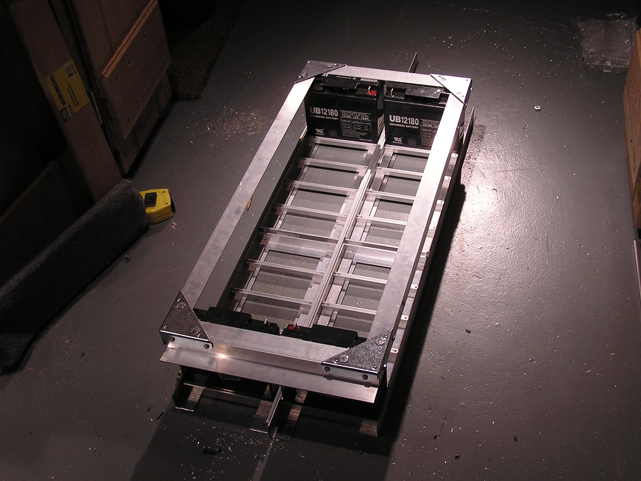
| 21:44, 20 March 2007 | Entire alt batt box mounting supports.jpg (file) |  |
622 KB | Alt. mounting method. Shows supports with trays in place. | 1 |
| 21:42, 20 March 2007 | Rubber on center batt box support.jpg (file) |  |
629 KB | Alt mounting method. Shows rubber pads on the battery box support. | 1 |
| 21:41, 20 March 2007 | Left side battery box supports alt method.jpg (file) |  |
622 KB | Alt mounting method. Shows left side of battery box supports | 1 |
| 21:40, 20 March 2007 | Right side battery box supports alt method.jpg (file) |  |
633 KB | Alt. mounting method. Shows right side of supports | 1 |
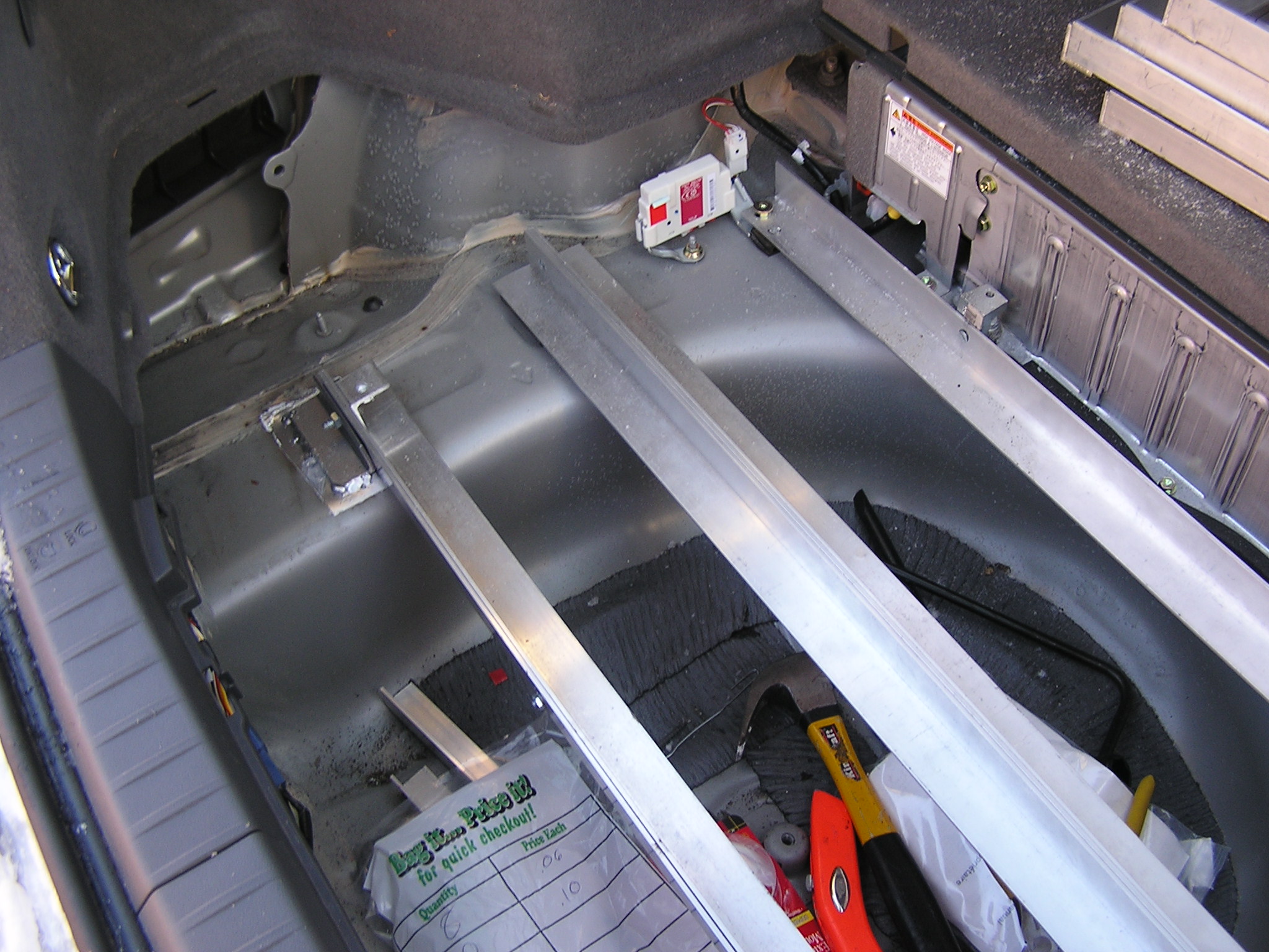
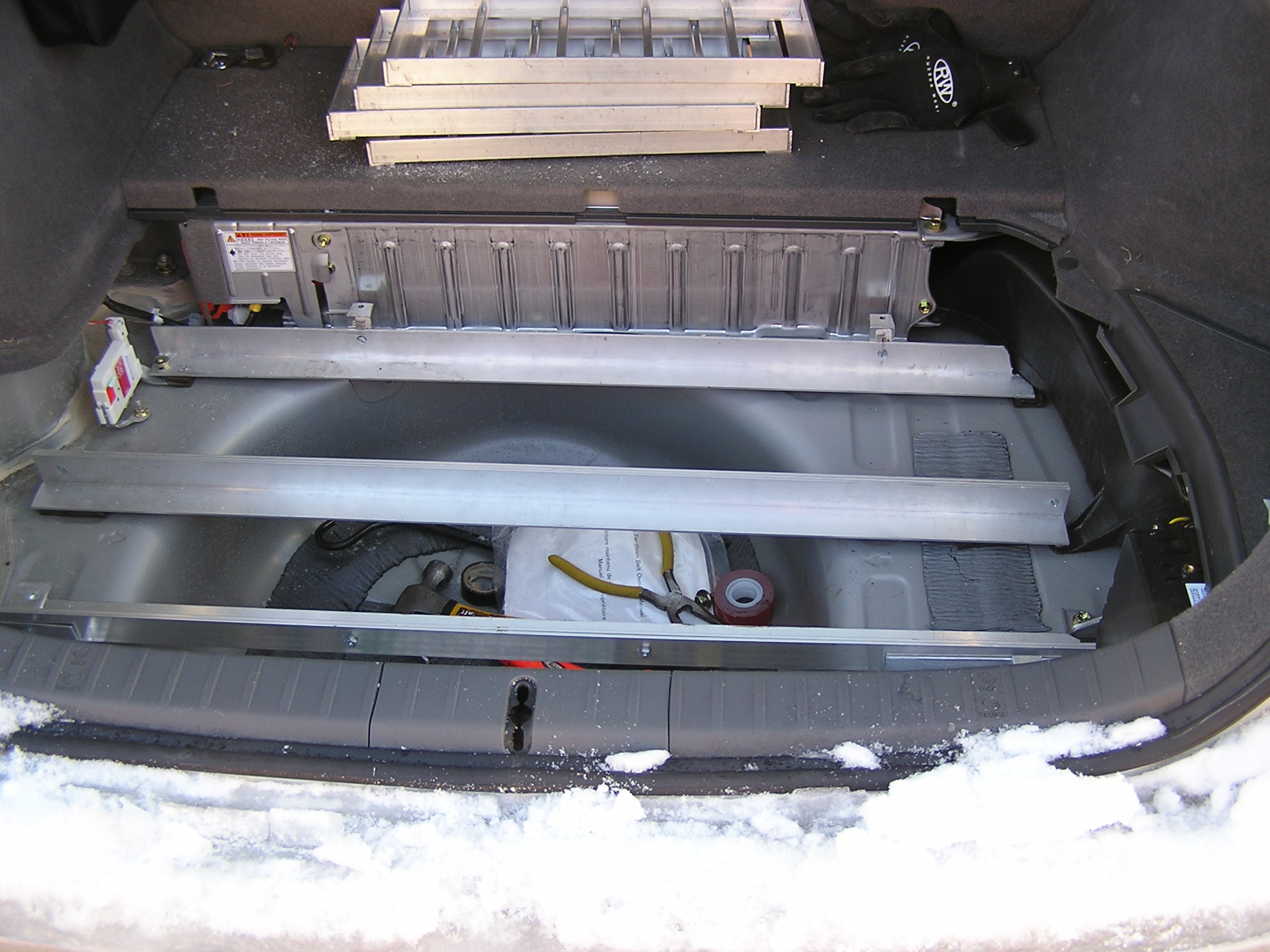
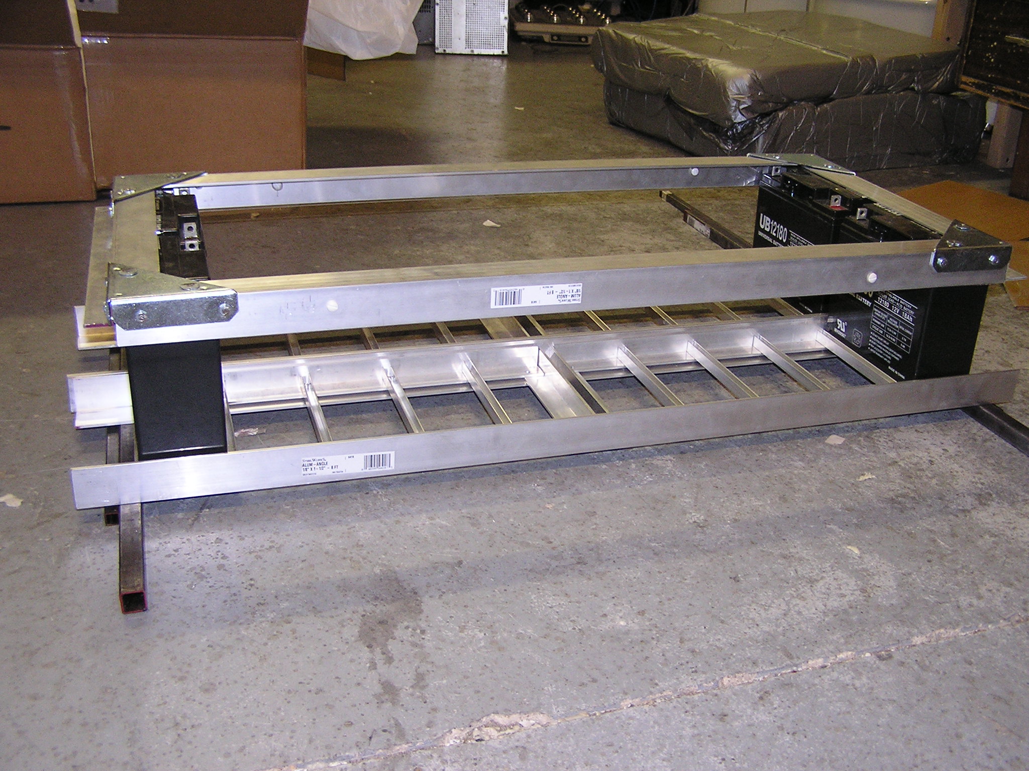
| 21:39, 20 March 2007 | Alt method support angle irons.jpg (file) |  |
614 KB | Alt. mounting method showing all angle irons (does not have angle iron on center support yet. | 1 |
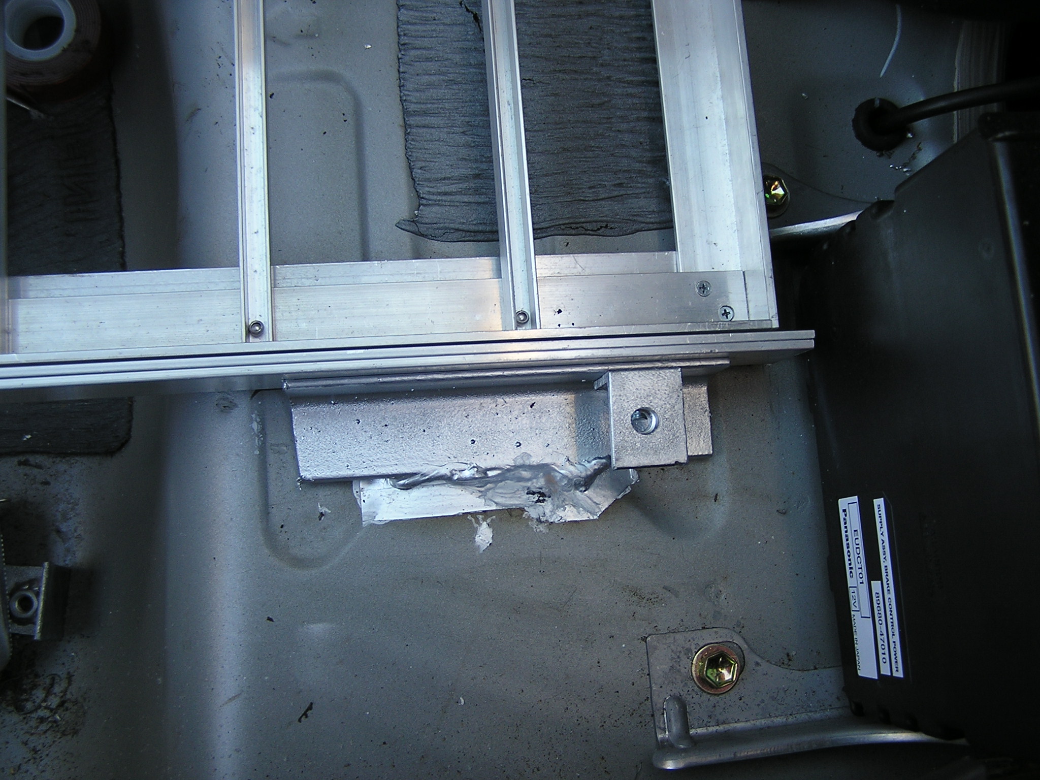
| 21:37, 20 March 2007 | Welded angle iron 2.jpg (file) |  |
647 KB | Shows just the welded angle iron for alt. mounting method | 1 |
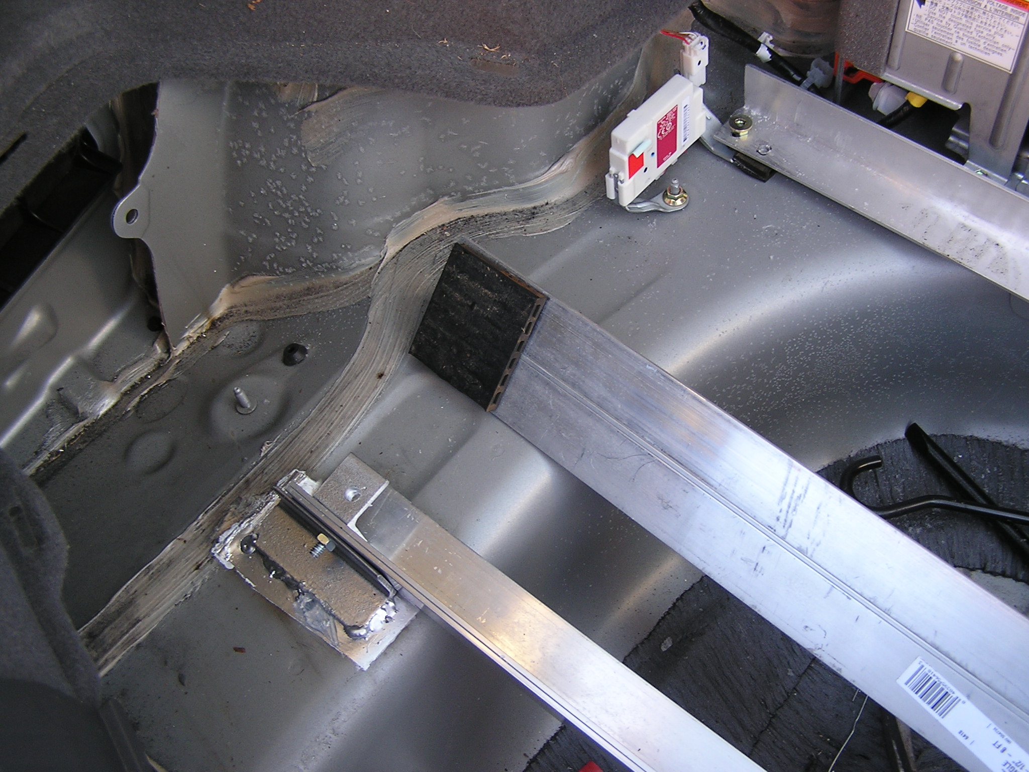
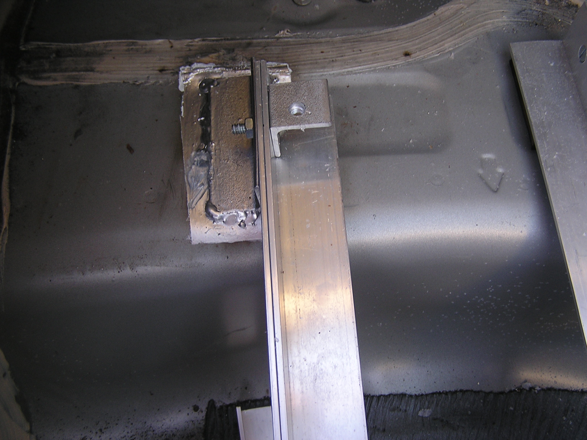
| 21:36, 20 March 2007 | Welded angle iron 1.jpg (file) |  |
637 KB | The welded steel angle iron is supporting the aluminum angle irons that support the battery box. | 1 |
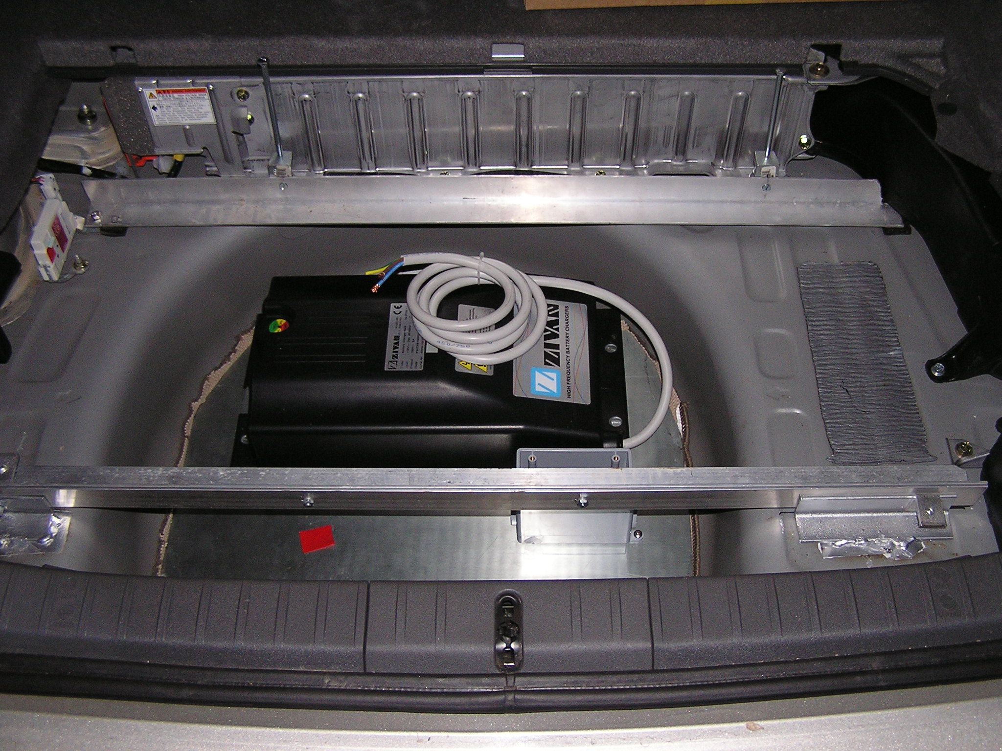
| 19:49, 20 March 2007 | Charger in tirewell.JPG (file) |  |
703 KB | Alt. mounting method. Charger is in tire well on steel sheet. Also shows outter batt box supports | 1 |
| 04:15, 13 February 2007 | Batt box test fit forward design.JPG (file) |  |
696 KB | Test fitting (and partially mounted) battery box. The battery box is moved as forward as possible. | 1 |
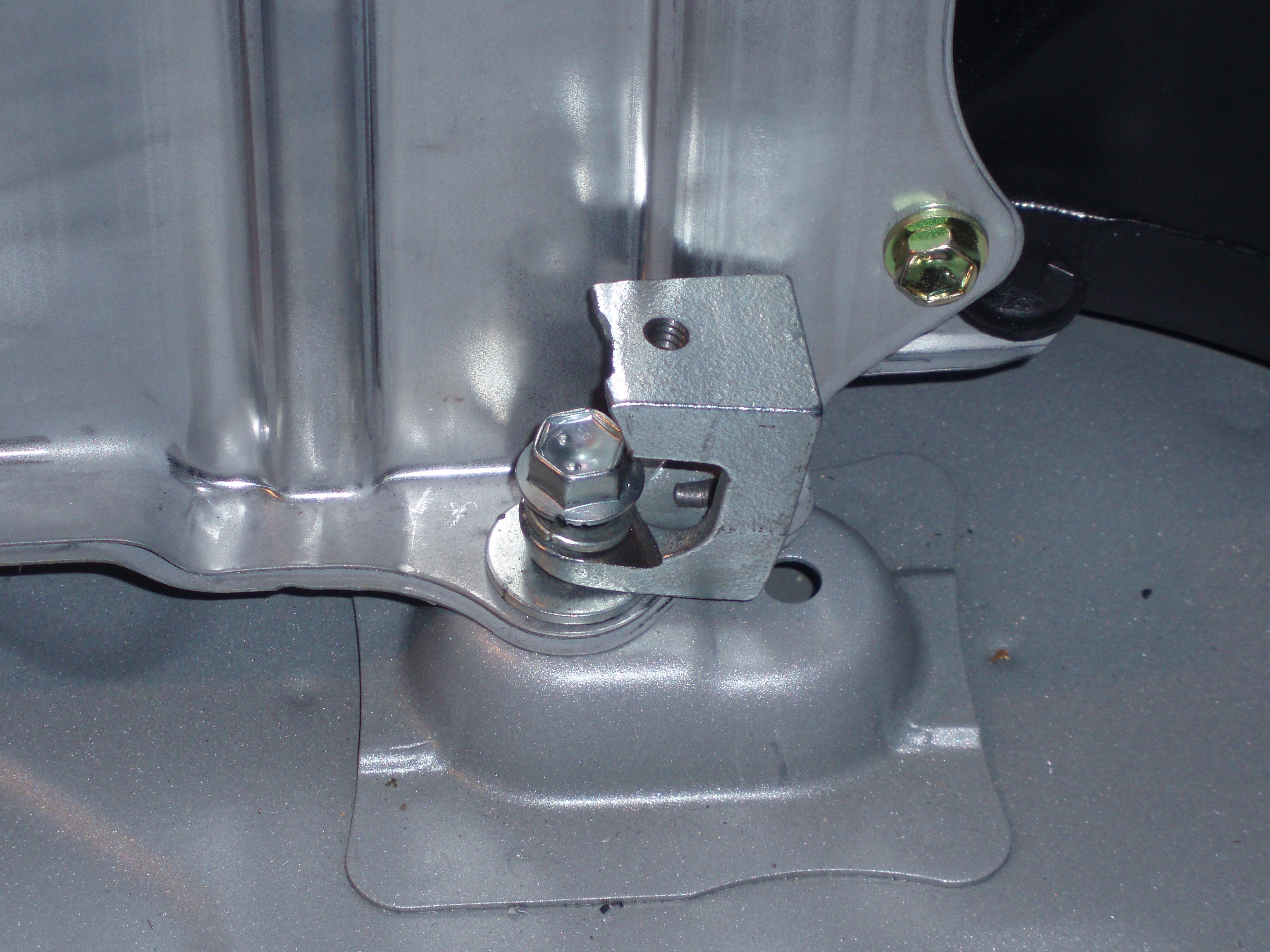
| 04:13, 13 February 2007 | Bracket on OEM Batt screw.JPG (file) |  |
1.42 MB | Bracket on OEM battery mounts I used to hold down new battery box | 1 |
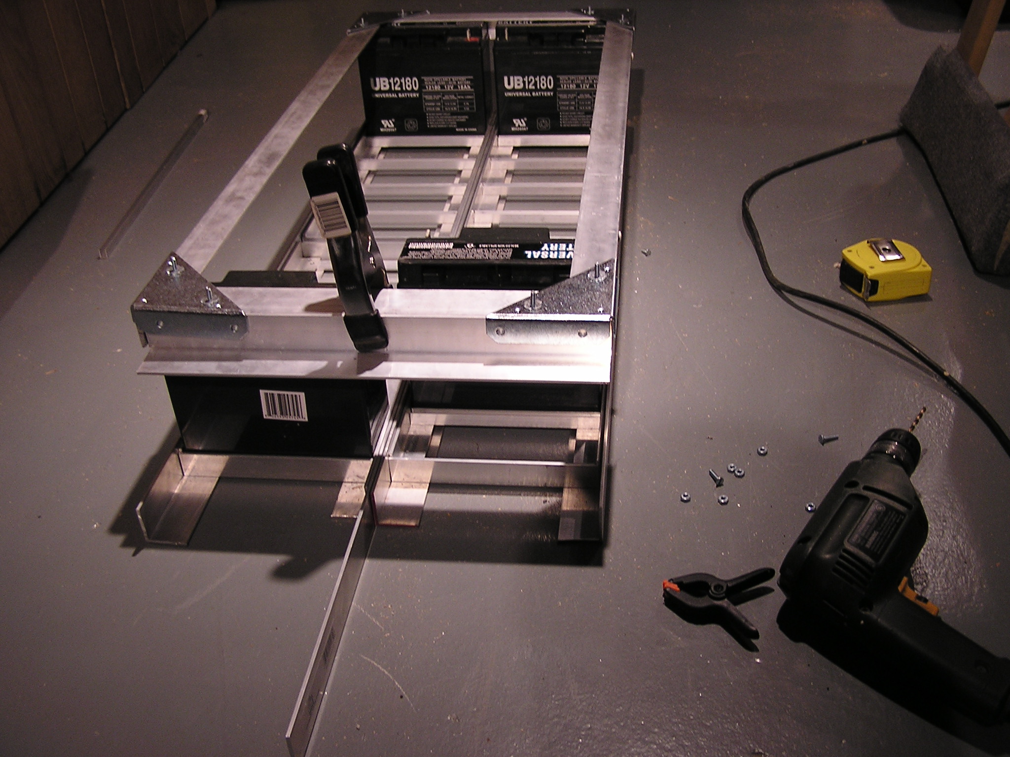
| 04:09, 13 February 2007 | Batt Box with screw lift supports.JPG (file) |  |
705 KB | Battery box set together with supports for screw lift idea | 1 |
| 04:07, 13 February 2007 | P1240040.JPG (file) |  |
693 KB | Battery box from side set together | 1 |
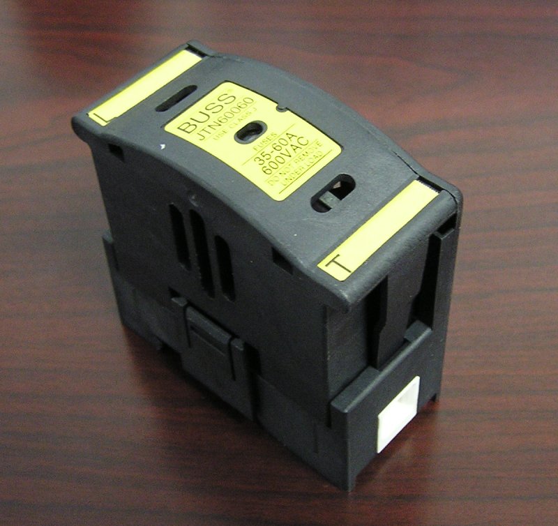
| 19:44, 12 January 2007 | JTN60060 Fuse Holder.JPG (file) |  |
97 KB | JTN60060 Fuse Holder | 2 |
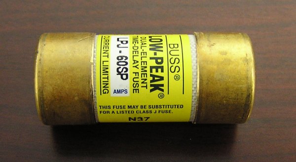
| 19:39, 12 January 2007 | LPJ-60SP.JPG (file) |  |
42 KB | The 60 amp LPJ-60SP fuse | 1 |
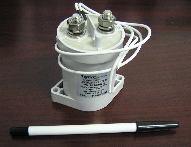
| 19:06, 12 January 2007 | EV200 Contactor.JPG (file) |  |
84 KB | The Kilovac EV200A4ANA (EV200) contactor | 1 |
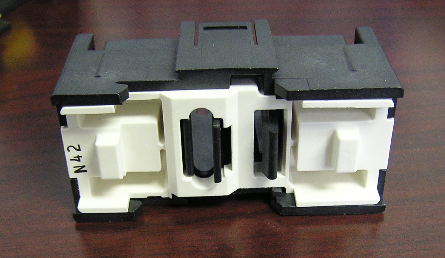
| 19:05, 12 January 2007 | Bottom of JTN60060.JPG (file) |  |
220 KB | Bottom of the fuse holder | 1 |
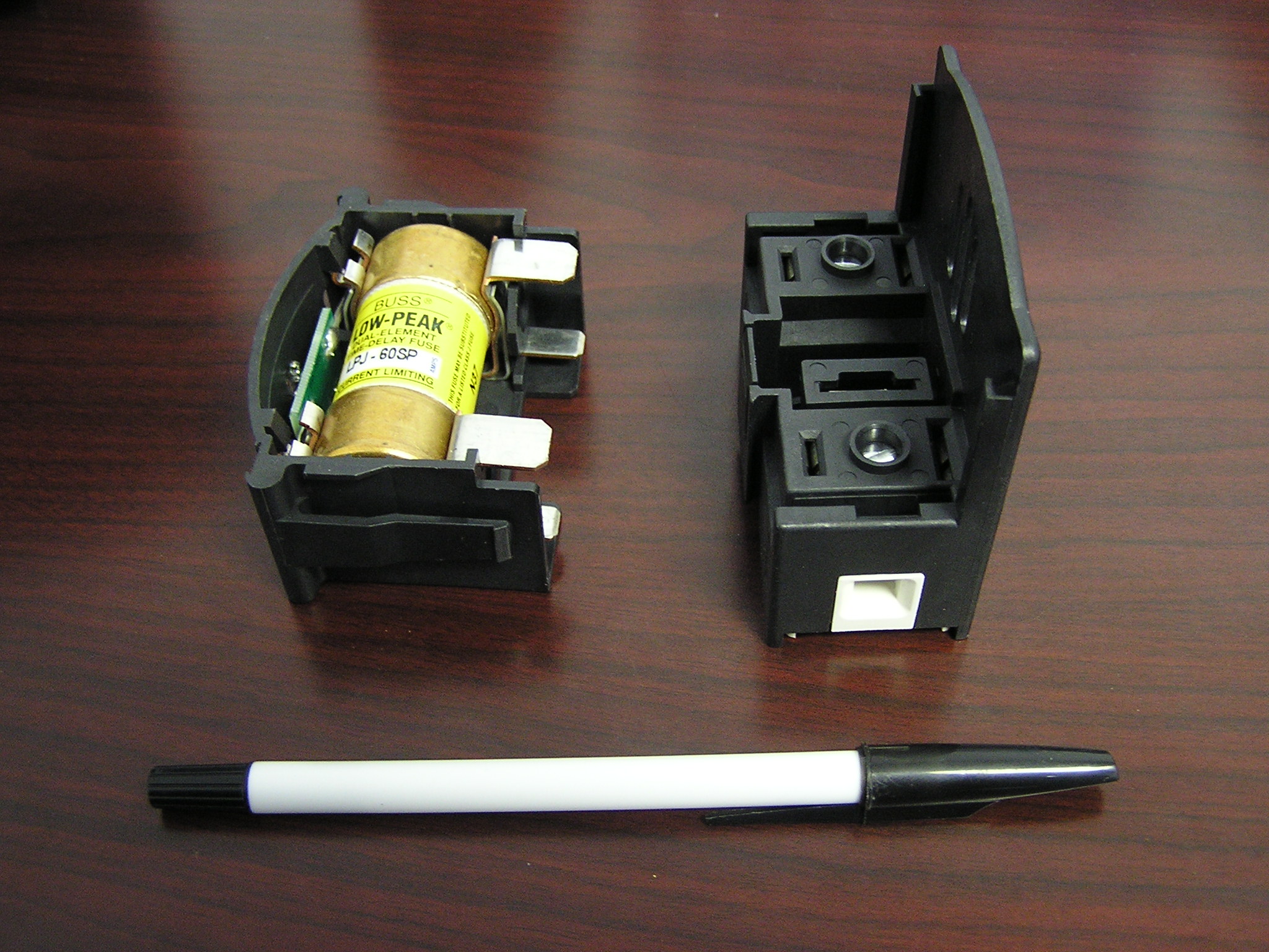
| 19:03, 12 January 2007 | Fuse in holder.JPG (file) |  |
727 KB | Installing the fuse into the holder | 1 |
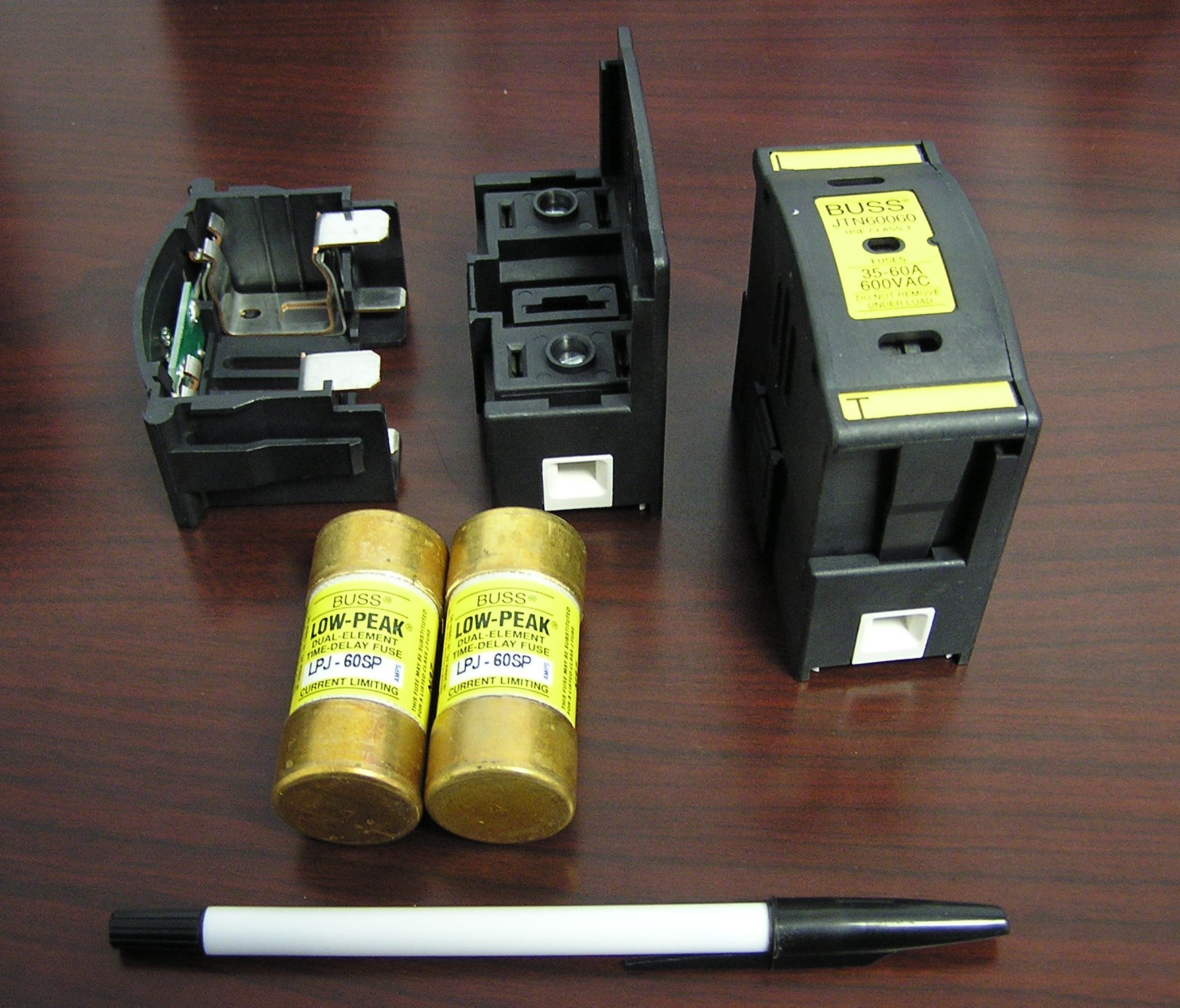
| 19:01, 12 January 2007 | Fuses and Holders.JPG (file) |  |
485 KB | The fuses and holders | 1 |
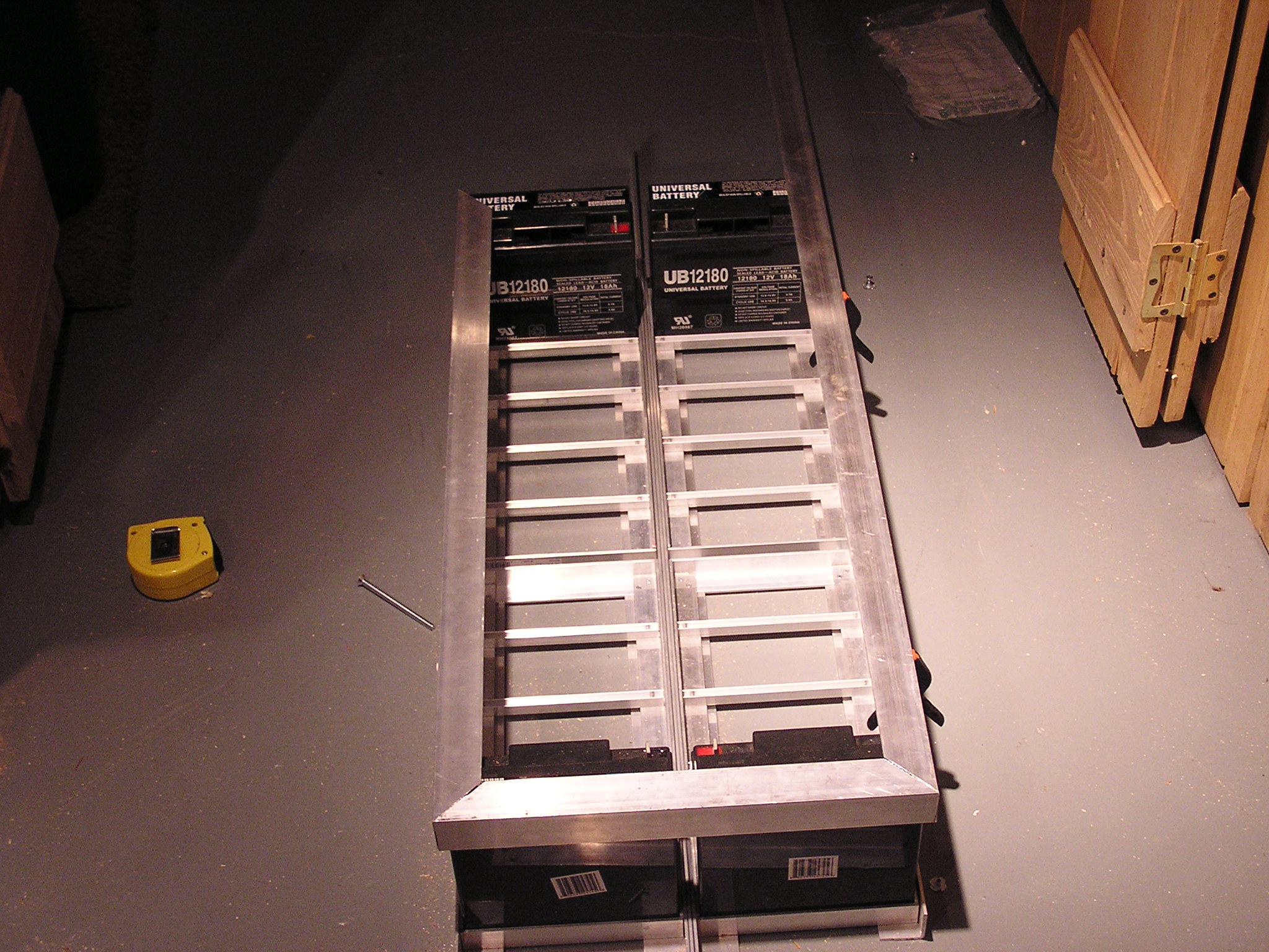
| 23:02, 17 December 2006 | Mostly Finished Batt Box.JPG (file) |  |
661 KB | Mostly finished battery box. Holes still need to be drilled into the angle irons to bolt down, and bolts will be added in the middle between the trays to bolt the top of the pack to the bottom. Also, mounting frame is not completely cut to size. | 1 |
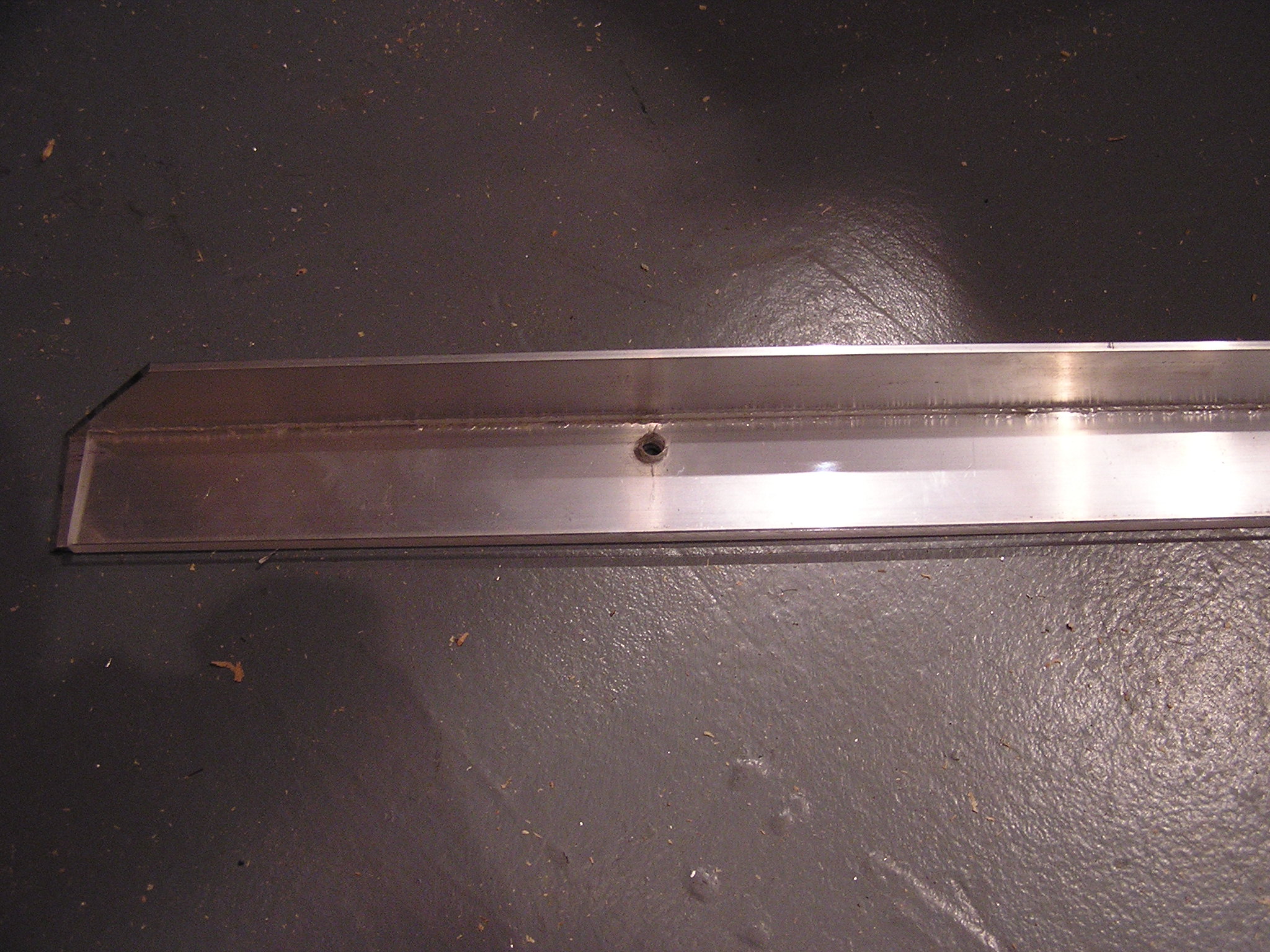
| 23:00, 17 December 2006 | Batt Box with Bolt Down Angle.JPG (file) |  |
676 KB | Shows the aluminum angle iron that sicks out of each side to bolt the battery box top down to the car. Waiting to drill holes until it is actually mounted. | 2 |
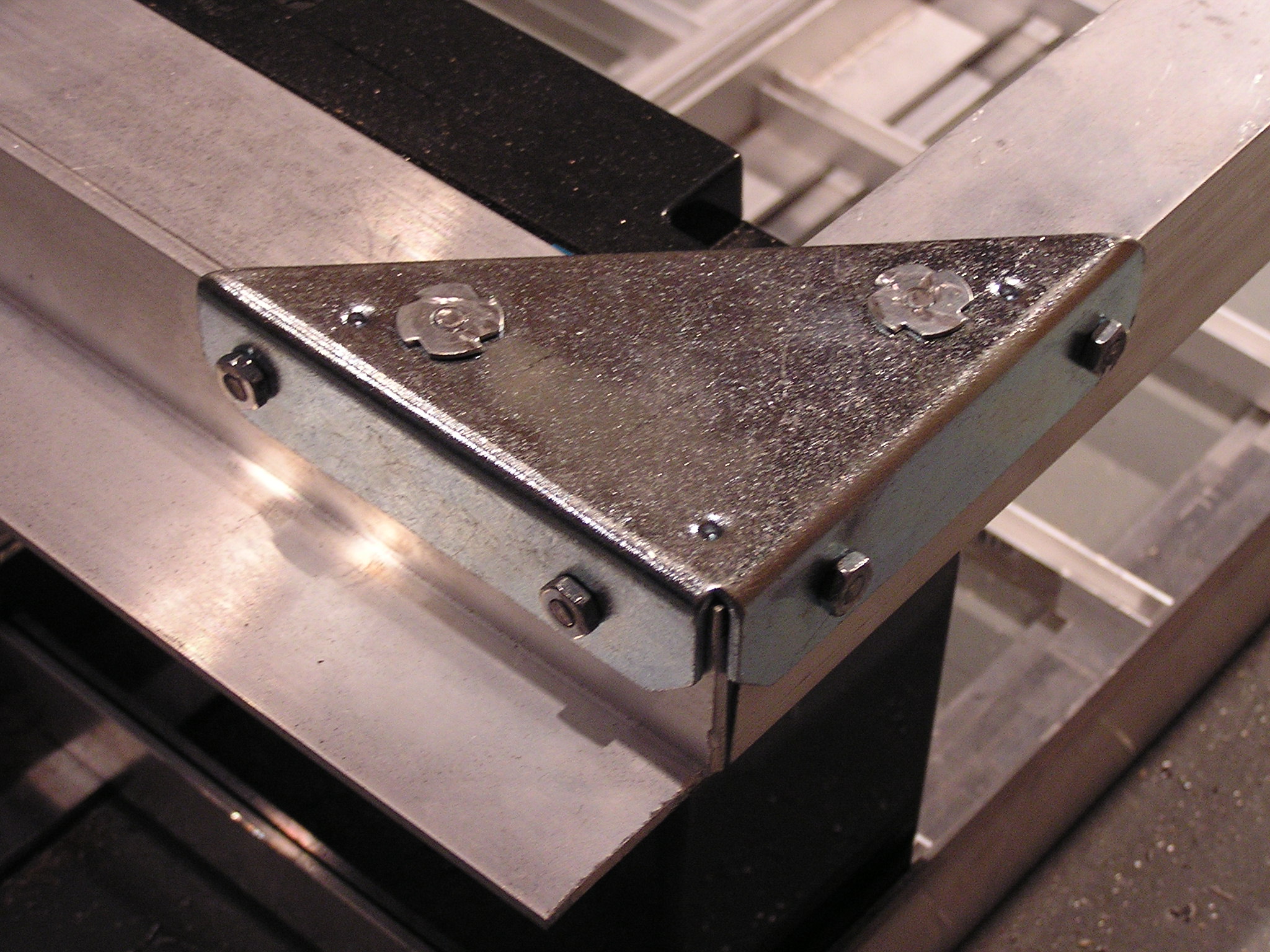
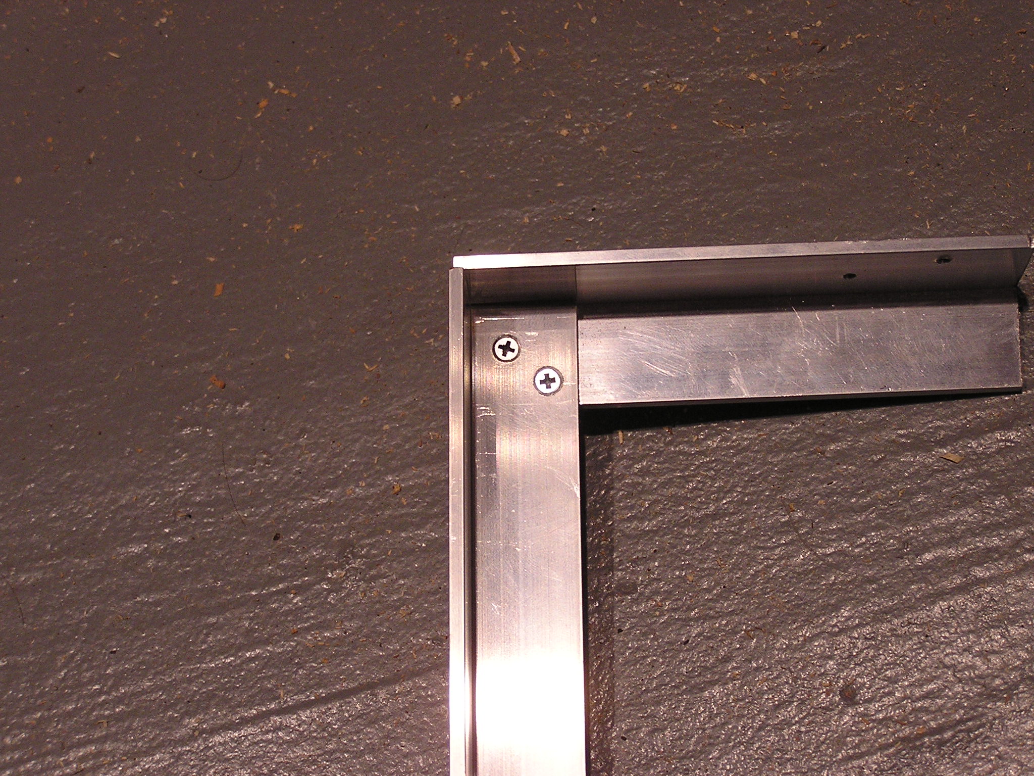
| 22:57, 17 December 2006 | Finished Corner.JPG (file) |  |
685 KB | Finished corner with ground of screws. I'm pretty sure this isn't done the official CalCars method. | 1 |
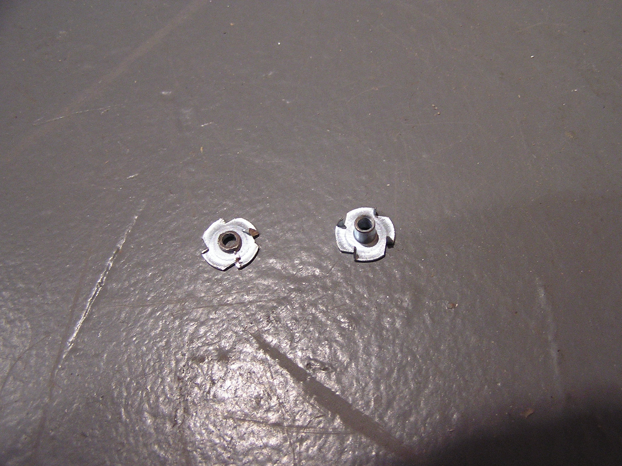
| 22:56, 17 December 2006 | Binding Posts Ground Down.JPG (file) |  |
716 KB | These are the binding posts I choose to use. The one on the left is ground down to fit and the burs are also ground off. I'm sure there is a better way to do this, but it worked. | 1 |
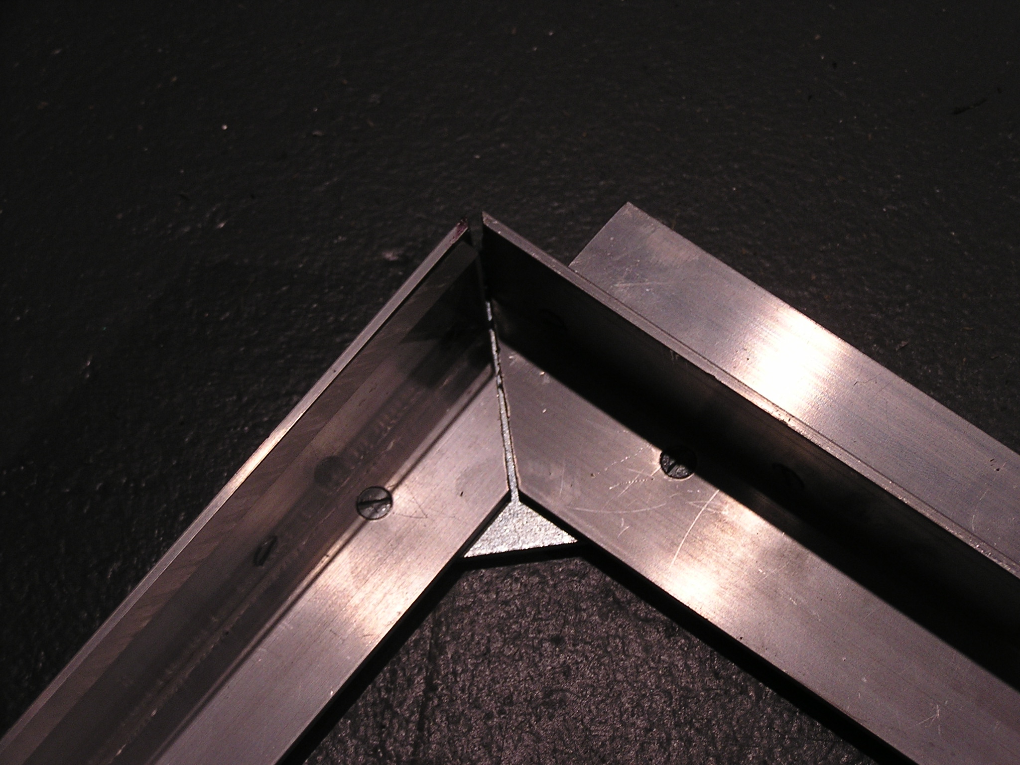
| 22:54, 17 December 2006 | Inside Corner.JPG (file) |  |
635 KB | Inside the corner bracket. The machine screws are counter sunk into the aluminum angle iron. | 1 |
| 22:51, 17 December 2006 | Plexiglass Shield.JPG (file) |  |
717 KB | I choose to install a plexiglass 'shield' on the side of the aluminum angle iron to reduce the risk of a wire / terminal hitting the aluminum and arcing. I am not sure if that is in the official CalCars plans or not. It is held in by non-conductive nylo | 1 |
| 22:43, 17 December 2006 | Batt Box Top 3 Angles.JPG (file) |  |
696 KB | Aluminum angle irons cut with 45 degree angles and laid on top of the battery box | 1 |
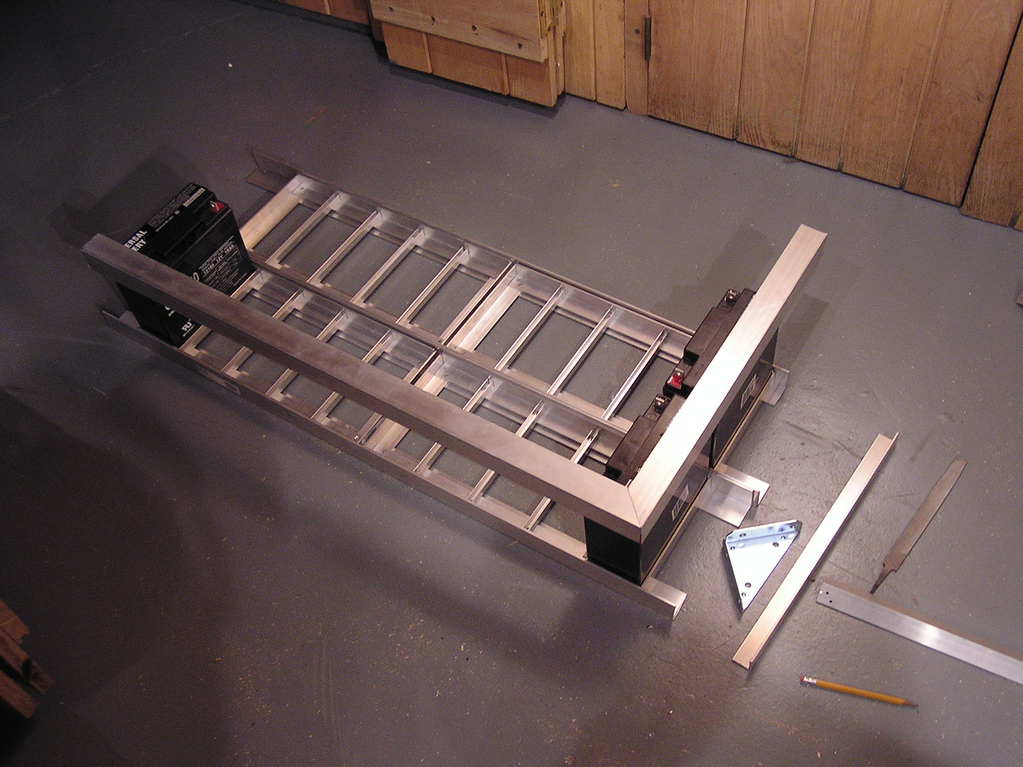
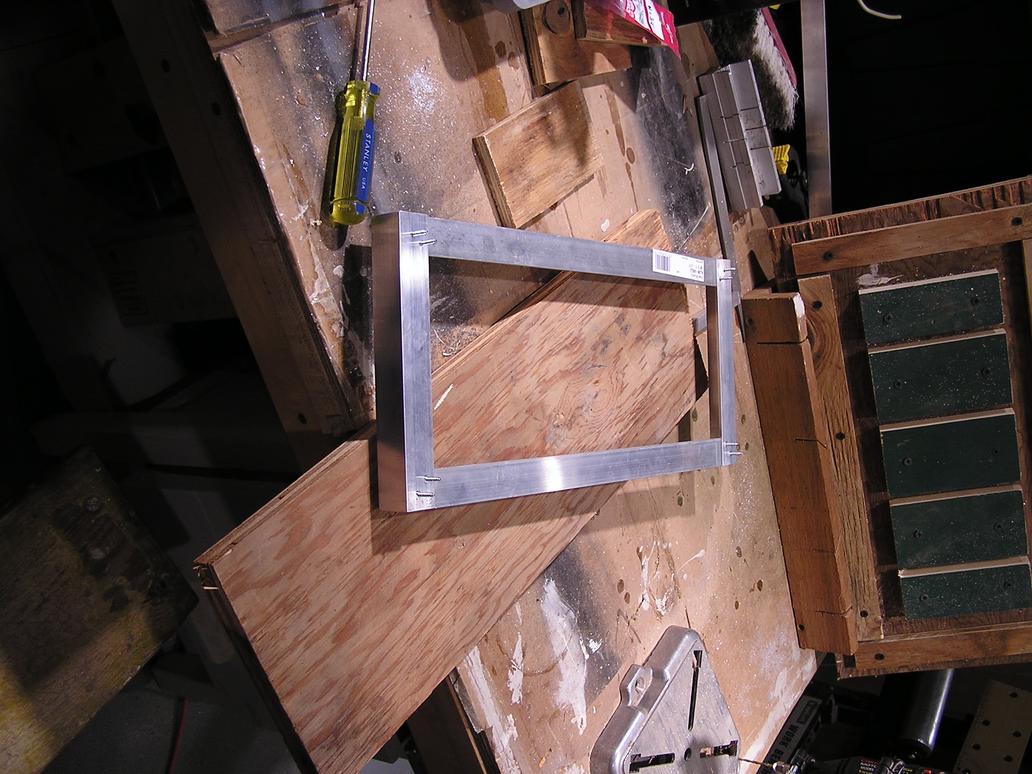
| 05:34, 15 December 2006 | Top Battery Box With Corner Bracket.JPG (file) |  |
718 KB | Corner bracket is just sitting on the top of the battery box waiting to be screwed down. | 1 |
| 05:33, 15 December 2006 | Top Battery Box 45 Degree Cuts.JPG (file) |  |
728 KB | The aluminum angle irons are cut with 45 degree angles so they fit snugly | 1 |
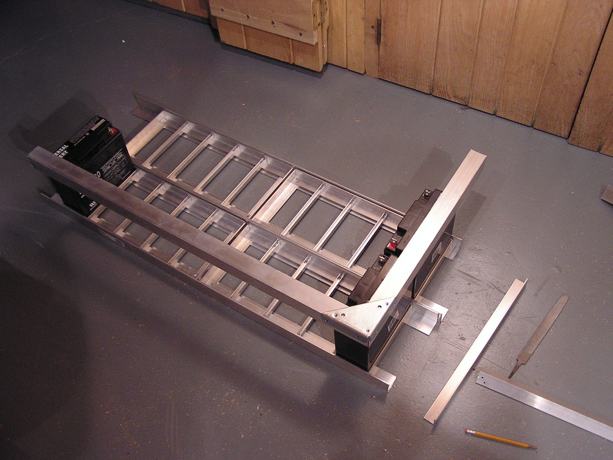
| 05:31, 15 December 2006 | Starting on the Top of Battery Box.JPG (file) |  |
723 KB | Bottom is mostly assembled, now starting on cutting the angle irons for the top. | 1 |
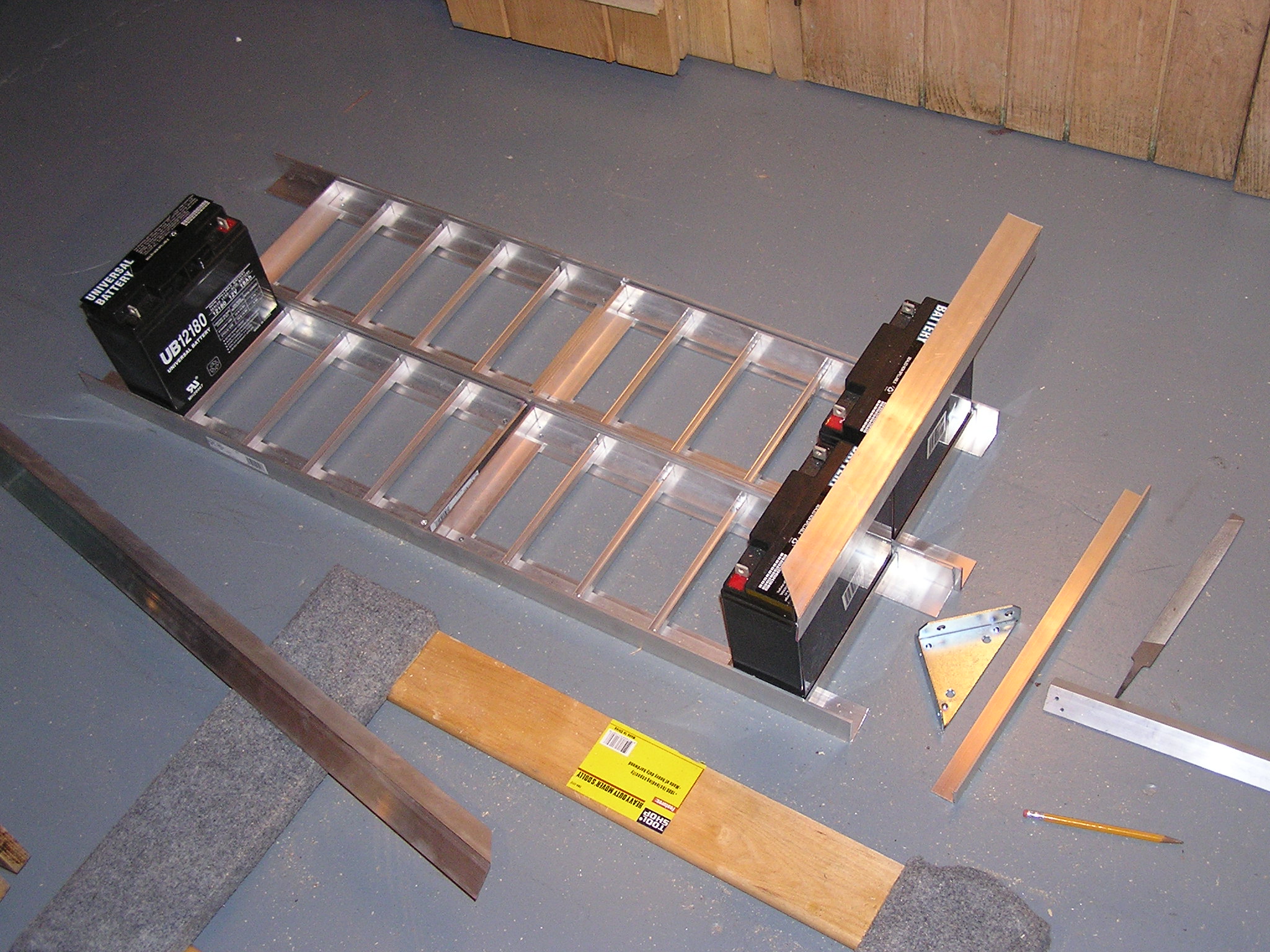
| 05:29, 15 December 2006 | 2 Trays with Some Supports.JPG (file) |  |
752 KB | 2 of the trays sitting on 2 1-1/2 angle irons (others just sitting there) | 1 |
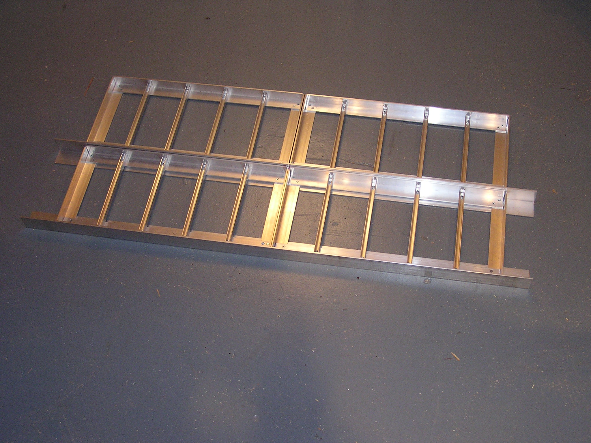
| 05:19, 15 December 2006 | 4 Finished Trays.JPG (file) |  |
746 KB | 1 | |
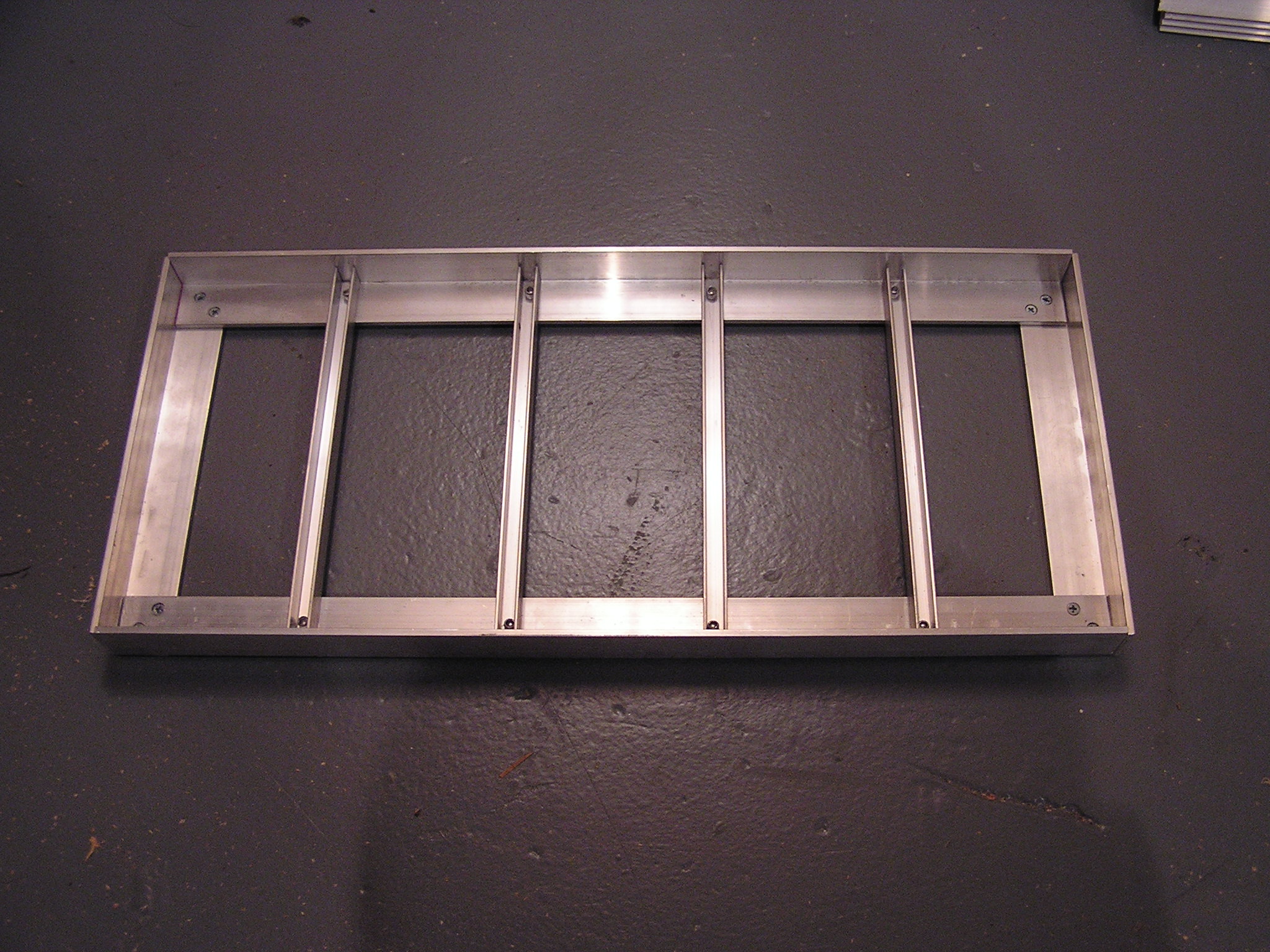
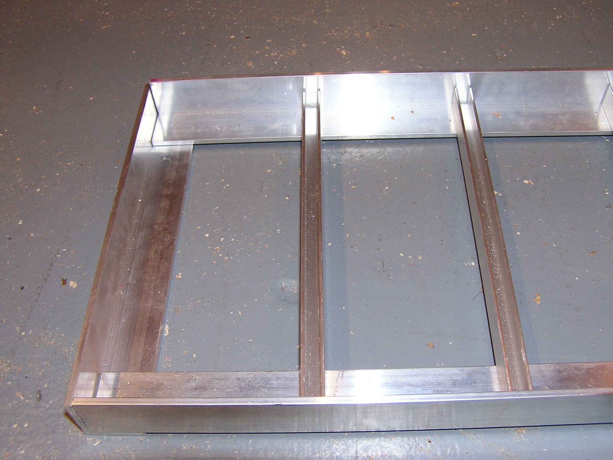
| 05:18, 15 December 2006 | Finished Tray.JPG (file) |  |
712 KB | 1 | |
| 05:17, 15 December 2006 | Screws Sticking Through Partially Assembled Tray.JPG (file) |  |
616 KB | I used extra long, self threading screws, so they stick through. I used a hacksaw first, and then a dremel with a metal cut off attachment to cut the screws at the base. Then used a grinder to grind them perfectly flat. | 1 |
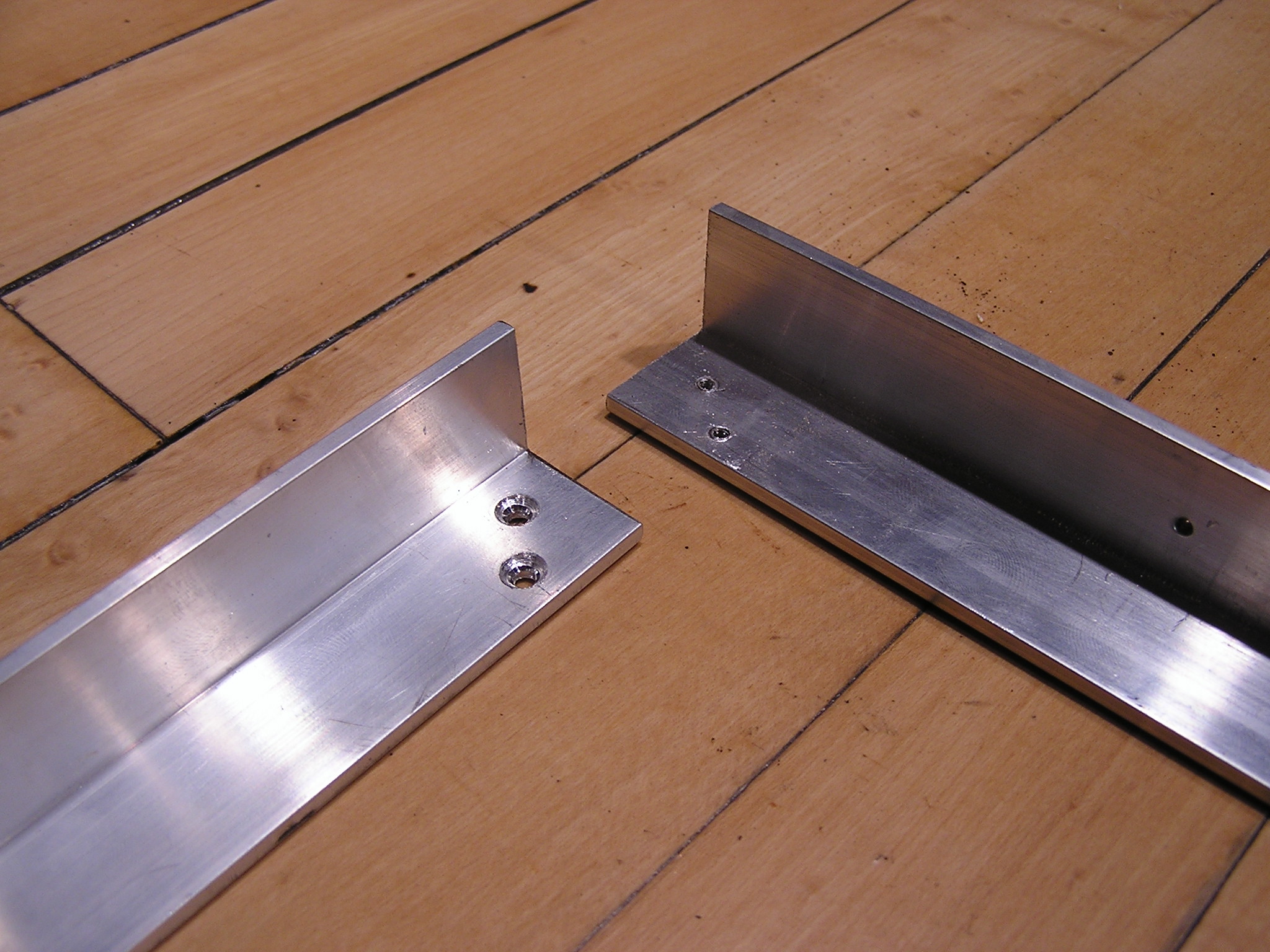
| 05:14, 15 December 2006 | Closeup of Sample Finished Corner.JPG (file) |  |
705 KB | This is just a sample I tried on a scrap pieces before doing the real thing. | 1 |
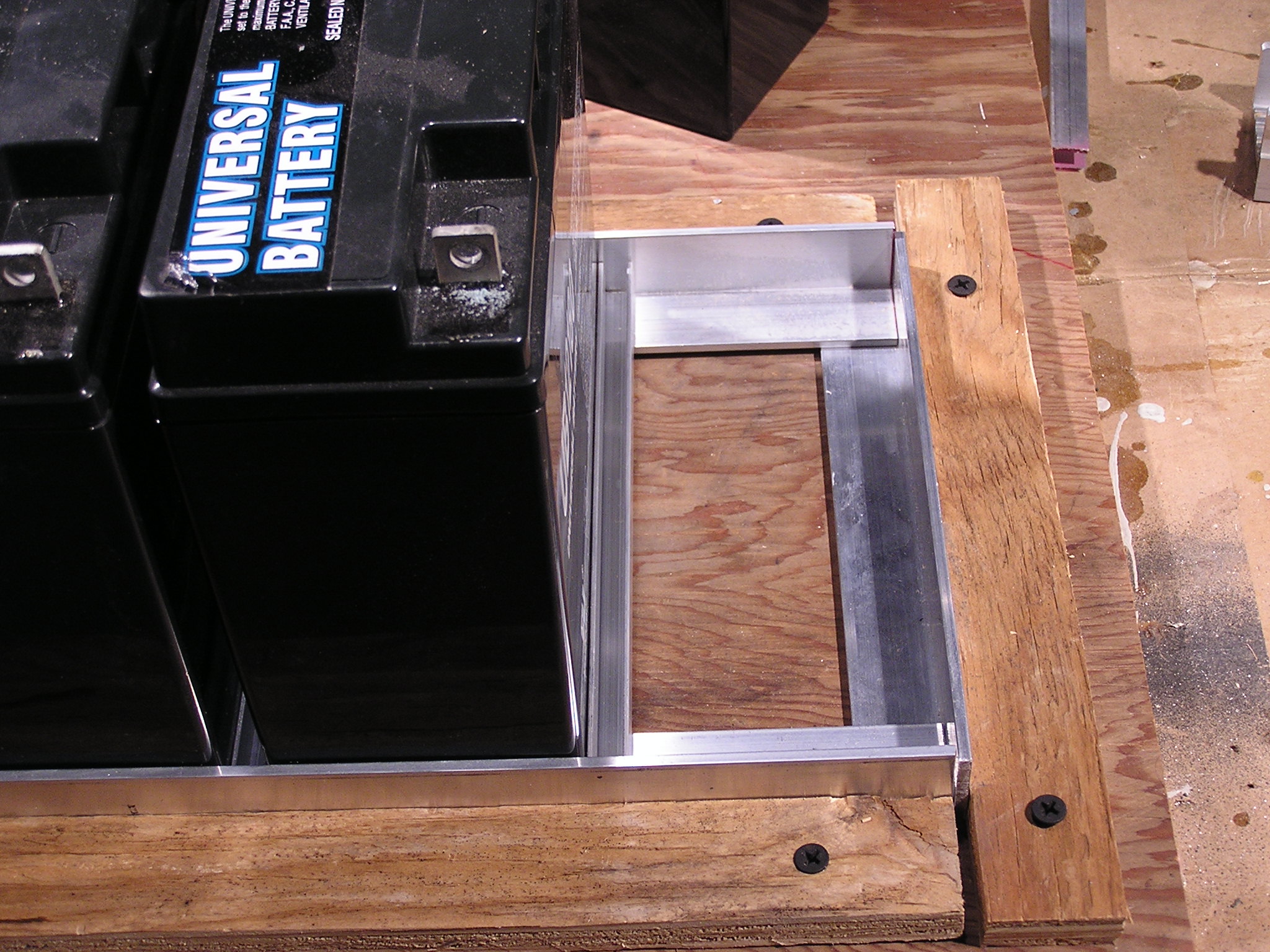
| 05:12, 15 December 2006 | Holes drilled in aluminum.JPG (file) |  |
665 KB | Holes drilled in the aluminum. Used the dremel to drill through both angle irons in the same place, then drilled a larger hole in the top (so the screw would go through without threading and then countersunk it with a much larger drill bit. | 1 |
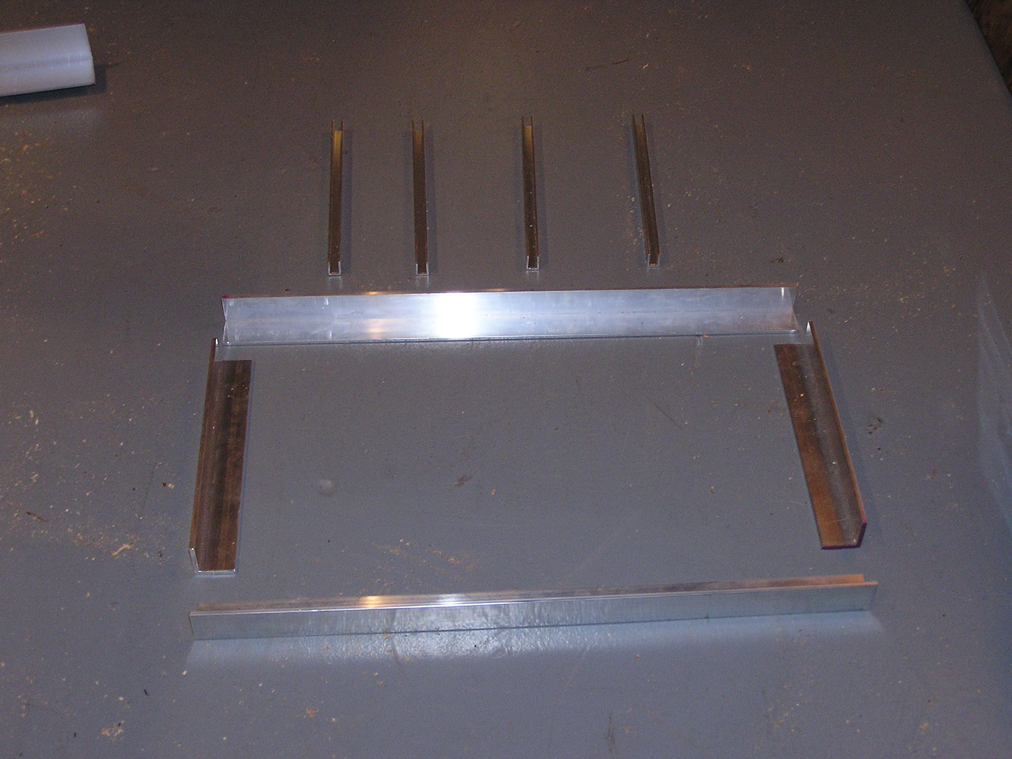
| 05:10, 15 December 2006 | Tray Parts Laid Out.JPG (file) |  |
721 KB | All the parts of one tray laid out | 1 |
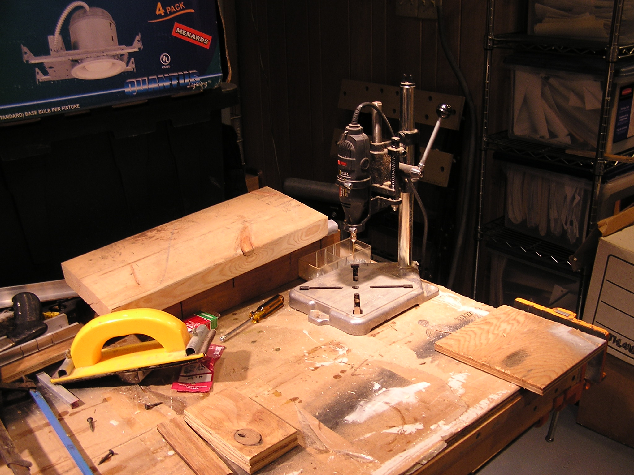
| 05:08, 15 December 2006 | Dremel Drill Press.JPG (file) |  |
604 KB | This is the Dremel drill press I used to drill the small holes in the angle irons. | 1 |
| 05:06, 15 December 2006 | Almost Finished Tray Jig.JPG (file) |  |
633 KB | 1 | |
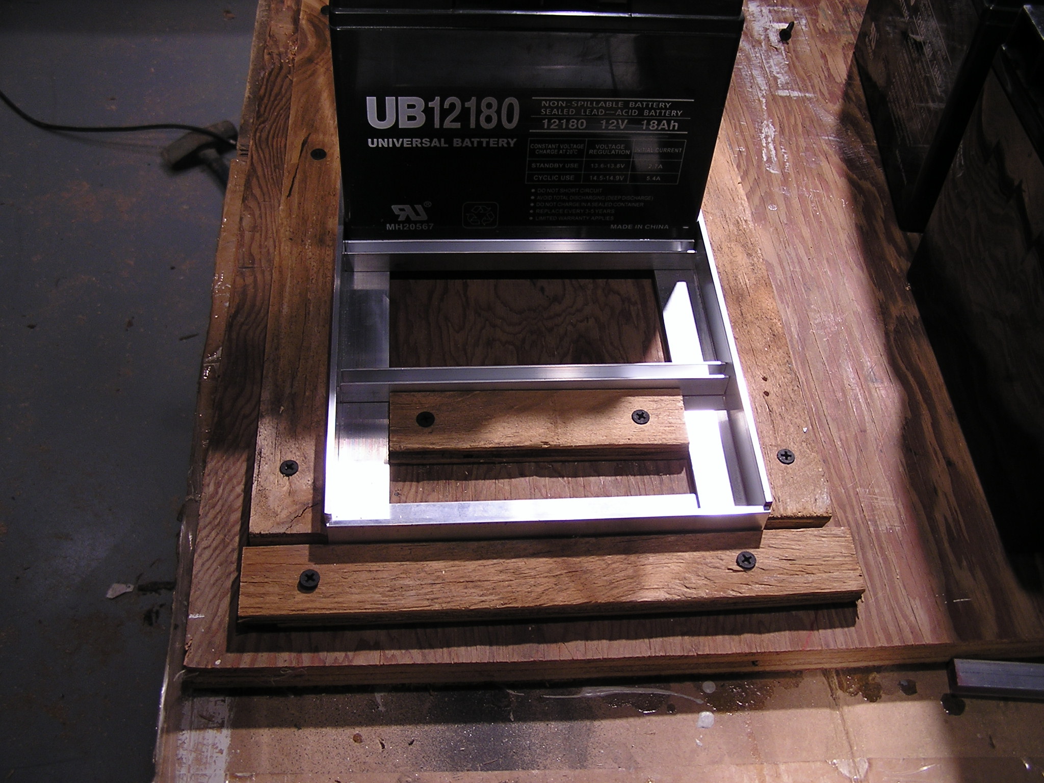
| 05:04, 15 December 2006 | Making Tray Jig Step 3.JPG (file) |  |
623 KB | Place wood to hold the channel irons in place | 1 |
| 05:02, 15 December 2006 | Making Tray Jig Step 1.JPG (file) |  |
665 KB | Step one is to place wood around the outsides of the angle iron to hold the angle irons in place. | 1 |
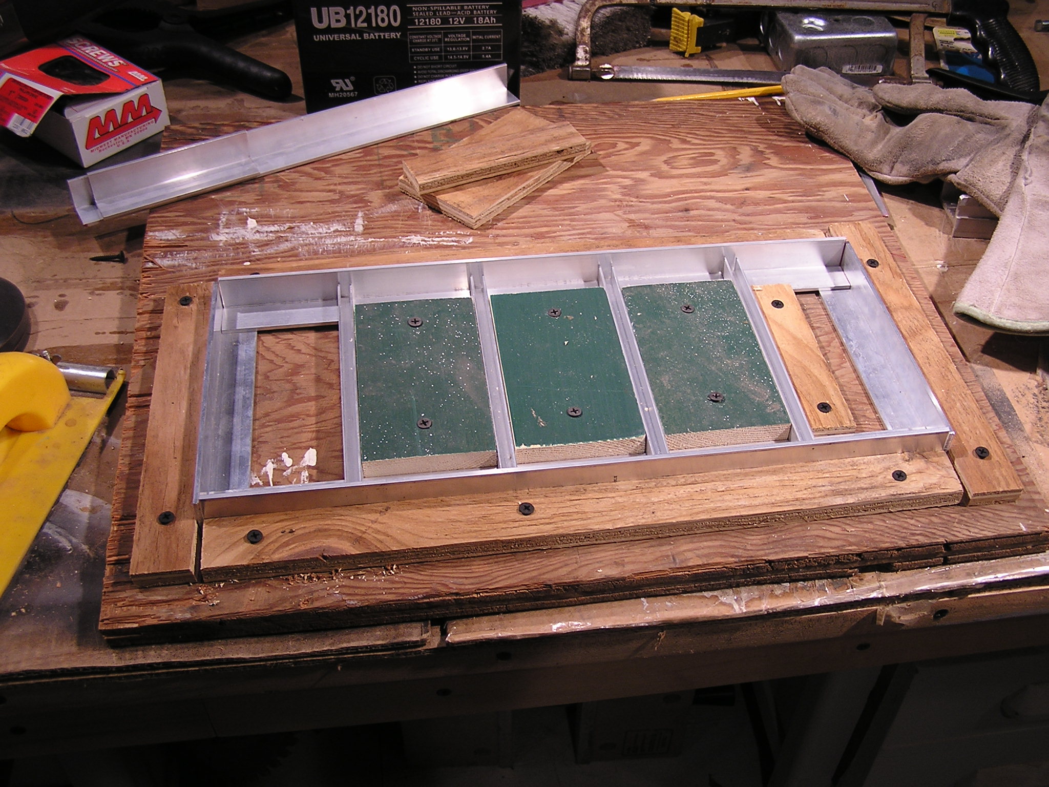
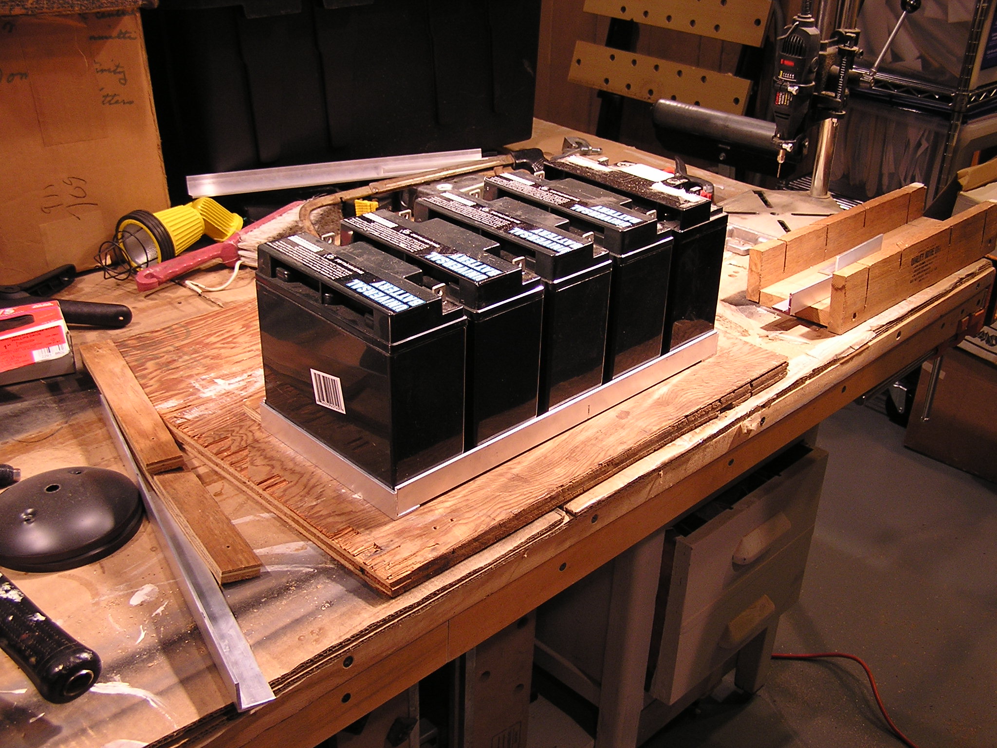
| 05:01, 15 December 2006 | Making Tray Jig Step 2.JPG (file) |  |
656 KB | The set together tray with batteries and wood secured in placed around the outsides to form the jig. | 1 |
| 04:58, 15 December 2006 | Tray Ready for Jig.JPG (file) |  |
674 KB | This photo is of the tray set together on a sheet of plywood (wich will be used as a jig to hold everything in place for drilling holes. | 1 |
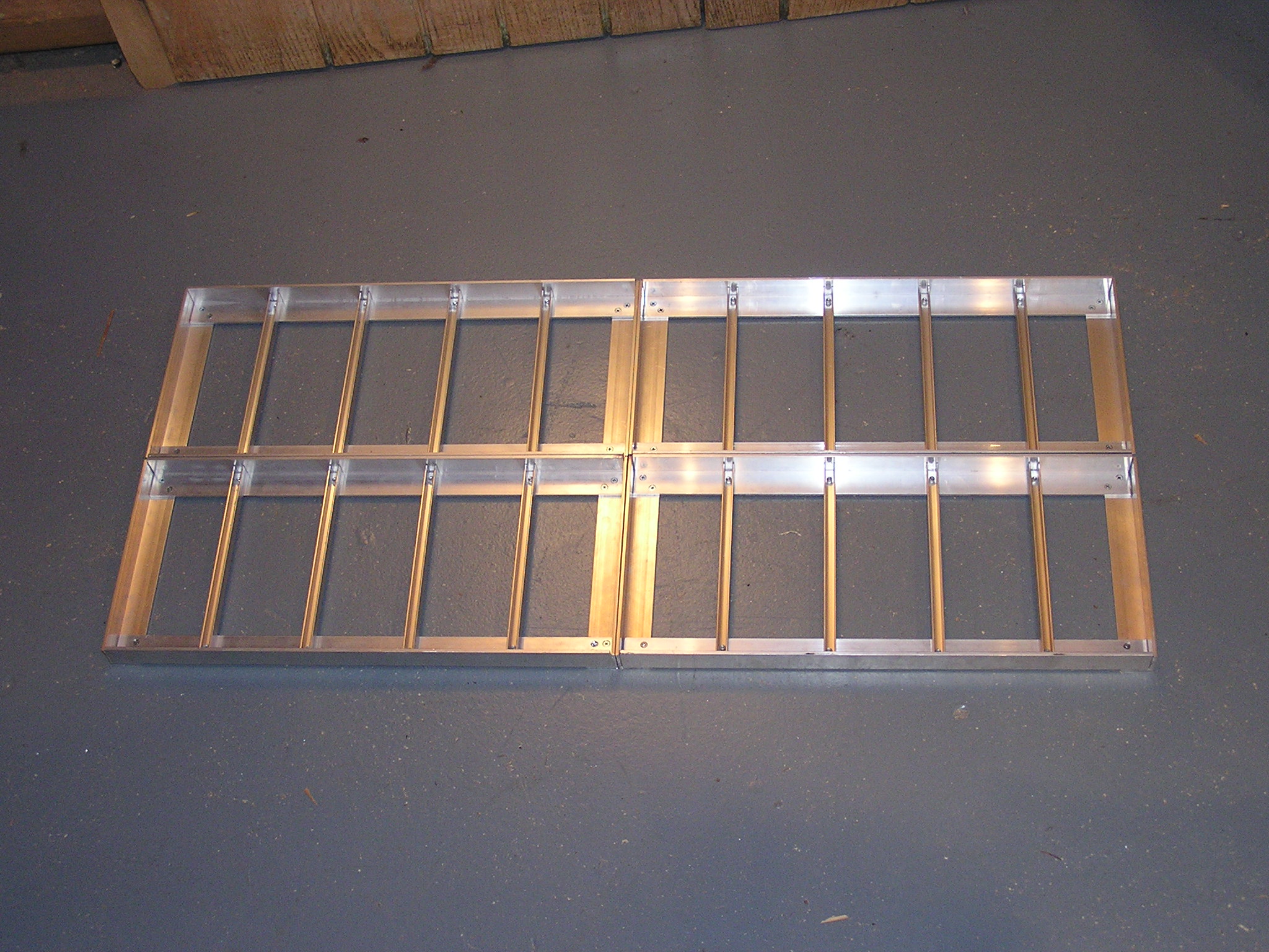
| 04:56, 15 December 2006 | Tray Set Together Close Up.JPG (file) |  |
693 KB | 1 | |
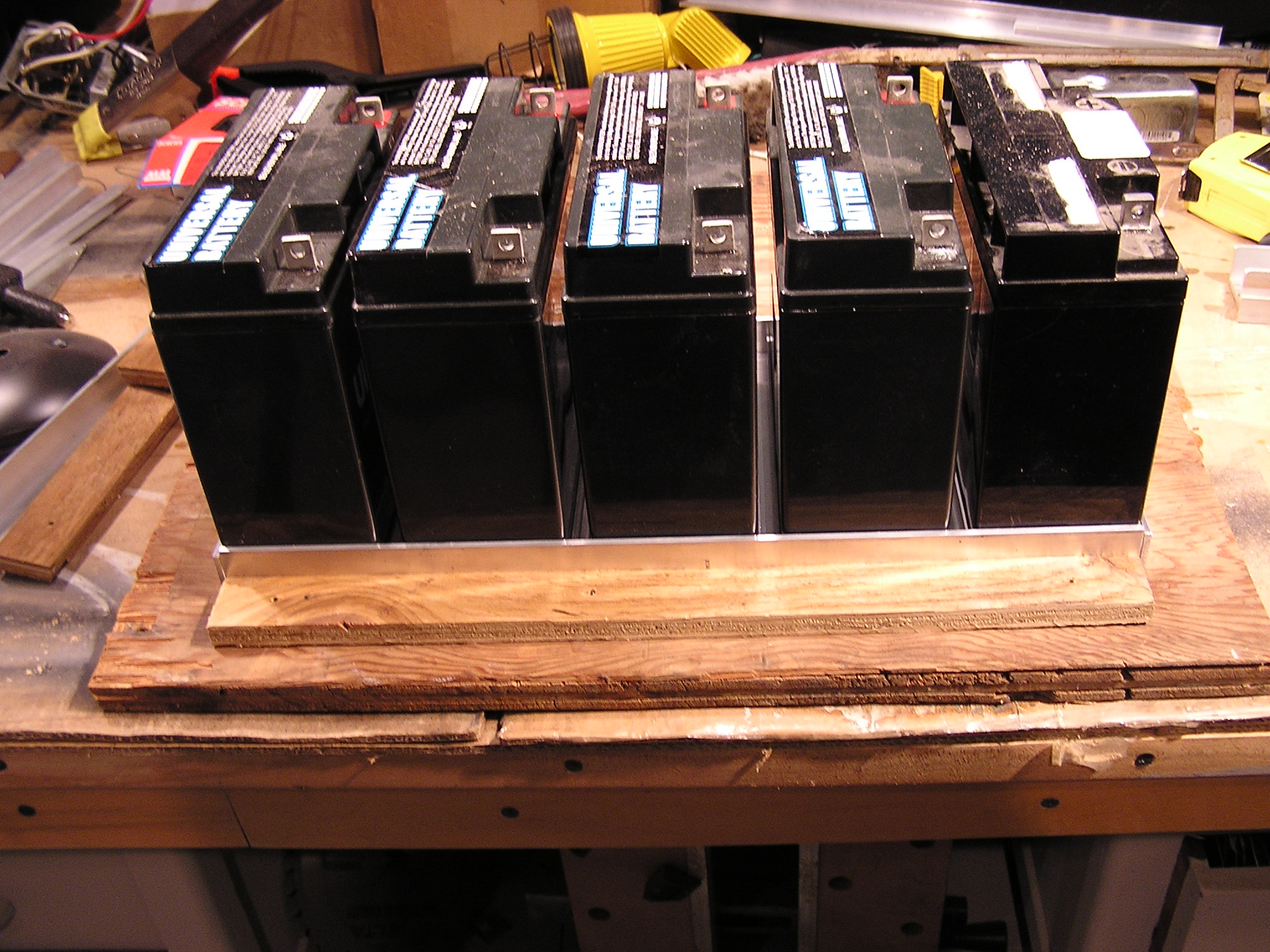
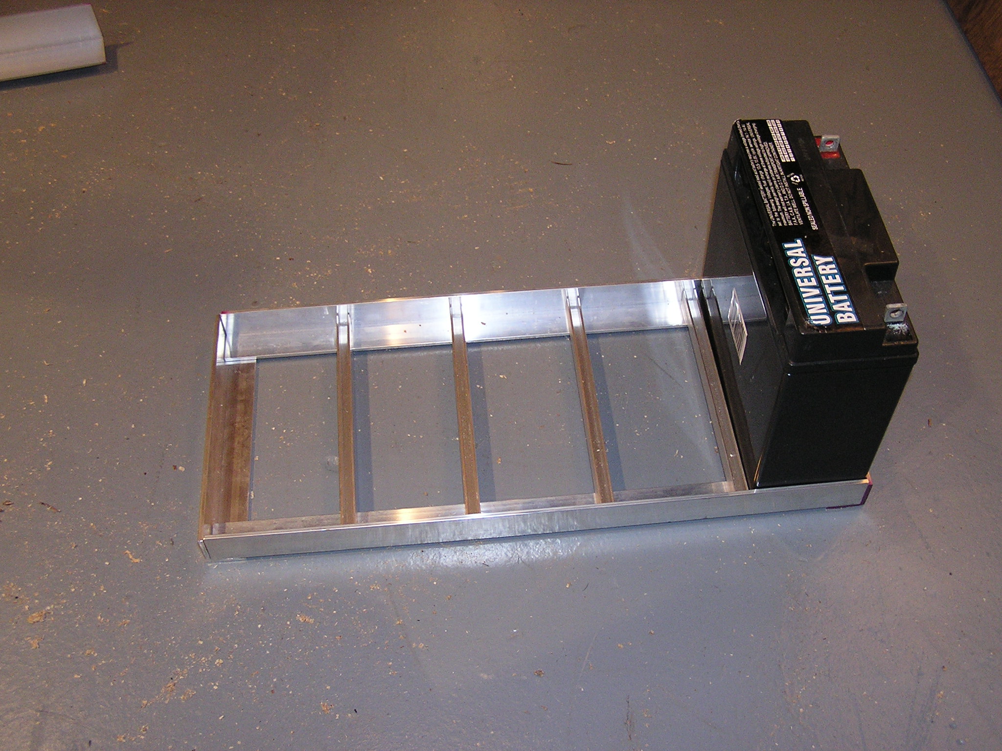
| 04:55, 15 December 2006 | Tray Set Together With Battery.JPG (file) |  |
725 KB | 1 | |
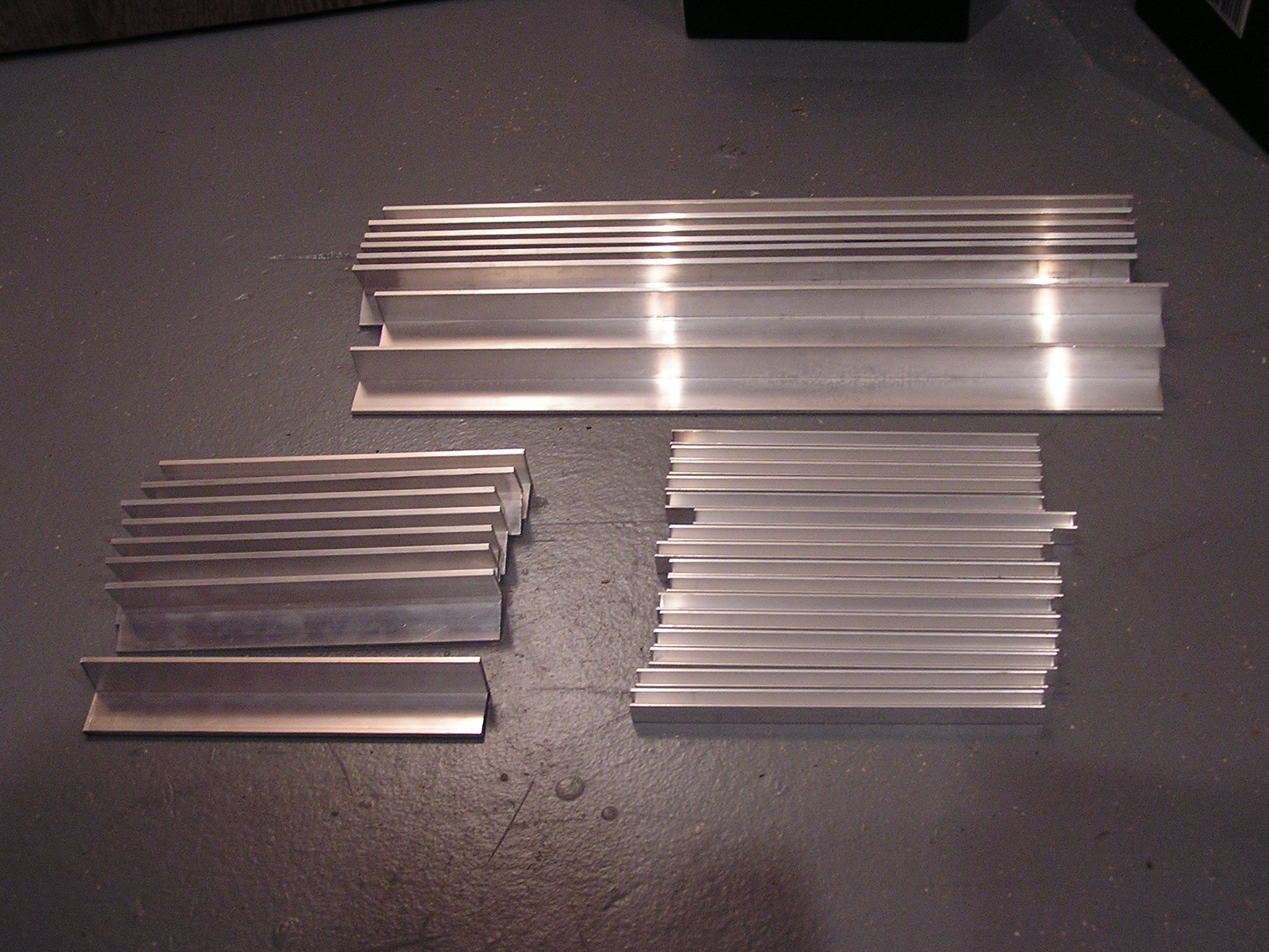
| 04:54, 15 December 2006 | Tray Pieces.JPG (file) |  |
704 KB | These are all the aluminum pieces needed to build the 4 battery trays. | 1 |
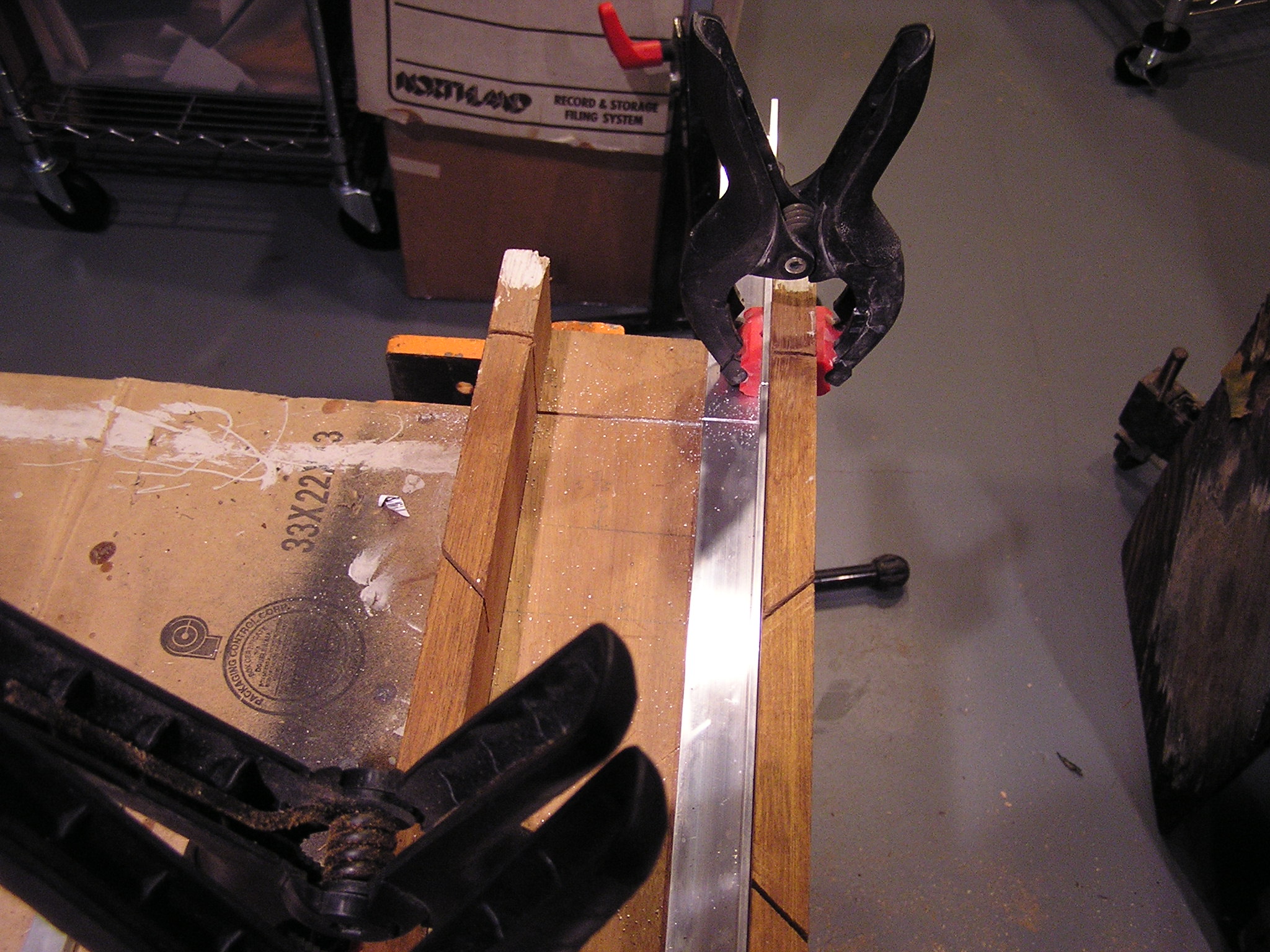
| 04:51, 15 December 2006 | Cutting Aluminum.JPG (file) |  |
704 KB | 1 |