|
General Disclaimer: (HV) (DC) injury or death hazard, use at your own risk, may void warranty. |
PriusPlus-Electronic
| Click show for a short list of the current PHEV conversion and kit options for the Toyota Prius. |
|---|
|
For Prius conversion details see the Prius PHEV article and comparisons table.
|
|
--={ Project Overview
}={ 2007 Maker Faire
}={ Theory
}={ Instructions
}={ Parts List
}={ RawData
}={ Latest News
}=--
|
|---|
|
--={ Historic }={ Battery }={ Schematics }={ PseudoCode }={ Photos }=-- |
 Team Photo from the PriusPlus conversion of Sven's Prius from Nov 2006. This is the home of the PRIUS+ PHEV DIY (Do-it-Yourself) documentation. These pages are currently anonymously editable, which may change in the future. Please feel free to use the Discussion page for general discussion and commentary on the main article. If you would like to add to an existing section use the "edit" link near that topic's heading. Don't forget to use the Summary field to describe your changes. While editing use the "Show Preview" button to make sure your changes look like you expect them to, before you click "Save Page". |
Intro Paragraph here maybe with a link to the main PriusPlus article, links to external sites can appear as formatted CalCars, just plain URLs like http://www.calcars.org, or fancy references such as that in the next paragraph.
Another Paragraph and such, you can get help at our Help:Contents#How do I use the Wiki Website page <ref>http://en.wikipedia.org/wiki/Help:Contents more help using the wiki.</ref> Feel free to simply remove or if you like move all of this example text to the pages discussion article.
Contents
Control Board

Approx. time requirement: 6-8 hours
A few issues have been found with the posted version of the control board schematics. The new version will be posted shortly with a corrected parts list.
Tools Needed
- Soldering Iron
- Solder
Parts List
The public DigiKey parts list for the control board can be found here
Parts list for Control Board Schematic
- Exported via OpenOffice from .xls to .html format, with minor changes by hand.
- See Image:EAA-PHEV-PRIUS-ControlBdPartsList.zip for the original document.
- DigiKey Parts List
| Parts List for CalCars' PRIUS+ Control Board V4.2 and LED Board V1.1 | ||||||
| Ronald Gremban, 1/21/2007 | ||||||
| Quantity | Value | DigiKey Number | Board Designators | Min Qty | Est Cost | Est Cost |
| Misc | Total | |||||
| 1 | 4.7nF Capacitor | 495-2555-ND | C5 | $0.13 | $0.13 | |
| 13 | 0.1uF Capacitor | 495-1147-ND | C6,C7,C14-18,C22-27 | $0.17 | $2.21 | |
| 6 | 0.47uF Capacitor | 495-1160-ND | C8-13 | $0.35 | $2.10 | |
| 1 | 22uF,20V Cap | P13461-ND | C4 | $0.11 | $0.11 | |
| 6 | 100uF,20V Cap | P13476-ND | C1-3,C19-21 | $0.14 | $0.84 | |
| 2 | 10PST DIP switch | CKN3028-ND | DIPSW1, DIPSW2 | $2.21 | $4.42 | |
| 2 | 15A blade fuse | F992-ND | F1,F2 | 5 | $0.46 | $2.30 |
| 2 | rt. angle socket | F064-ND (for blade fuses) | F1,F2 | $1.83 | $3.66 | |
| 1 | Omron SPDT Relay | Z785-ND (or DPDT Z790-ND, $7.58) | RL1 | $6.45 | $6.45 | |
| 1 | Relay Socket | Z792-ND socket | RL1 | $1.80 | $1.80 | |
| 1 | Relay holddown clip | Z796-ND (for Z792-ND socket) | RL1 | $0.28 | $0.28 | |
| Connectors | ||||||
| 4 | 2-pin 0.1" Molex | WM4200-ND | J6M,J7M,J10M,J20M | $0.34 | $1.36 | |
| 1 | 3-pin 0.1" Molex | WM4201-ND | J2M | $0.43 | $0.43 | |
| 9 | 2-pin 0.156" Molex | WM4620-ND | J11M–19M | $0.31 | $2.79 | |
| 1 | 3-pin 0.156" Molex | WM4621-ND | J3M | $0.41 | $0.41 | |
| 1 | 4-pin 0.156" Molex | WM4622-ND | J4M | $0.51 | $0.51 | |
| 1 | 5-pin 0.156" Molex | WM4623-ND | J8M | $0.41 | $0.41 | |
| 1 | 6-pin 0.156" Molex | WM4624-ND | J5M | $0.71 | $0.71 | |
| 1 | Jumper: 2-pin male | WM4000-ND | JP1 | $0.28 | $0.28 | |
| 1 | D15 female | 6215FE-nd | J1F | $2.41 | $2.41 | |
| 1 | 16-pin male ribbon | CHS16G-ND | J9M | $1.46 | $1.46 | |
| Semiconductors | ||||||
| 2 | 1N5404 | 1N5404-TPCT-ND | D1,D2 | 10 | $0.15 | $1.50 |
| 10 | 1N4004 | 1N4004-TPMSCT-ND | D3-9,D11-13 | 10 | $0.04 | $0.43 |
| 1 | MJE2955 | 497-2621-5-ND, TO-220 | Q1 | $1.04 | $1.04 | |
| 2 | MJE3055 | 497-2573-5-ND, TO-220 | Q16-17 | $0.99 | $1.98 | |
| 3 | 2N3904 | 2N3904FS-ND, TO-92 | Q2-3,Q15 | $0.11 | $0.33 | |
| 11 | TIP127 | TIP127FS-ND, TO-220 | Q4-14 | $0.63 | $6.93 | |
| 1 | STSA1805 | 497-3531-ND, TO-92 | Q18 | $1.13 | $1.13 | |
| 1 | 3mm grn LED | 511-1189-ND | D10 | $0.61 | $0.61 | |
| ICs | ||||||
| 1 | LM7812 | LM340T-12-ND | U9 | $1.66 | $1.66 | |
| 2 | CD4072 (14-pin DIP) | 296-2063-5-ND | U1,U2 | $0.55 | $1.10 | |
| 2 | CD4082 (14-pin DIP) | 296-2067-5-ND | U3,U4 | $0.55 | $1.10 | |
| 2 | CD4049 (16-pin DIP) | CD4049UBCN-ND | U5,U8 | $0.48 | $0.96 | |
| 1 | CD4081 (14-pin DIP) | 296-2066-5-ND | U6 | $0.55 | $0.55 | |
| 1 | LM339 | LM339ANFS-ND | U7 | $0.55 | $0.55 | |
| 6 | 14-pin DIP socket | AE10012-ND or ED90049-ND | U1-4,U6, U7 | $0.69 | $4.14 | |
| 2 | 16-pin DIP socket | AE7216-ND or ED90050-ND | U5,U8 | $0.72 | $1.44 | |
| Resistors | ||||||
| 1 | 330 | P330BACT-ND | R9 | 10 | $0.07 | $0.67 |
| 5 | 1K | P1.0KBACT-ND | R31,R34,R36,R38,R40 | 10 | $0.07 | $0.67 |
| 2 | 1.5K | P1.5KBACT-ND | R4,R5 | 10 | $0.07 | $0.67 |
| 1 | 2.2K | P2.2KBACT-ND | R3,R12 | 10 | $0.07 | $0.67 |
| 2 | 5.1K | P5.1KBACT-ND | R16,R22 | 10 | $0.07 | $0.67 |
| 2 | 6.2K | P6.2KBACT-ND | R17,R18 | 10 | $0.07 | $0.67 |
| 1 | 6.8K | P6.8KBACT-ND | R23 | 10 | $0.07 | $0.67 |
| 10 | 10K | P10KBACT-ND | R6,R10,R14,R28-30,R32-33,R35,R37 | 10 | $0.07 | $0.67 |
| 1 | 20K | P20KBACT-ND | R13 | 10 | $0.07 | $0.67 |
| 1 | 33K | P33KBACT-ND | R8 | 10 | $0.07 | $0.67 |
| 1 | 100K | P100KBACT-ND | R7 | 10 | $0.07 | $0.67 |
| 1 | 200K | P200KBACT-ND | R15 | 10 | $0.07 | $0.67 |
| 7 | 1M | P1.0MBACT-ND | R19-21,R24-27 | 10 | $0.07 | $0.67 |
| 1 | 10M | 10MEBK-nd | R11 | 5 | $0.05 | $0.26 |
| 1 | 2K pot | 490-2746-ND | R1 | $1.05 | $1.05 | |
| 1 | 5K pot | 490-2757-ND | R2 | $1.05 | $1.05 | |
| 2 | 100 | 770-63-R100P-ND (3 iso) | RN1,RN2 | $0.21 | $0.42 | |
| 2 | 10K | 770-81-R10KP-ND (7 bus) | RN3,RN12 | $0.34 | $0.68 | |
| 2 | 100K | 770-101-R100KP-ND (9 bus) | RN4,RN5 | $0.42 | $0.84 | |
| 4 | 1K | 770-63-R1KP-ND (3 iso) | RN6,RN7,RN10,RN11 | $0.28 | $1.12 | |
| 1 | 100K | 770-61-R100KP-ND (5 bus) | RN9 | $0.28 | $0.28 | |
| 147 | $74.87 | |||||
Assembly Steps

Solder the components to the printed board according to the schematics above. Make sure to install R3, D1 & D2 1/4 inches off the board and to solder the DIP sockets without the IC's installed. If new at soldering, make sure to use a heat sink for soldering transistors.
Installation
- See PriusPlus-Mechanical for instructions for physically mounting the control board.
Setup
Need instructions on how to adjust the pots for the correct temperature.
Troubleshooting
The LED board will provide useful information for debugging the control board.
LED Board

Approx. time requirement:
Tools Needed
- Soldering Iron
- Solder
Parts Needed
The public DigiKey parts list for the LED board can be found here
Parts list for LED Board Schematic
- Exported via OpenOffice from .xls to .html format, with minor changes by hand.
- See Image:EAA-PHEV-PRIUS-ControlBdPartsList.zip for the original document.
- DigiKey parts list
| Parts List for CalCars' PRIUS+ LED Board V1.1 | ||||||
| Ronald Gremban, 1/21/2007 | ||||||
| Quantity | Value | DigiKey Number | Board Designators | Est Cost | Est Cost | |
| Connectors | Total | |||||
| 1 | 16-pin male ribbon | CHS16G-ND (CHS116G was in error) | LJ1M | $1.46 | $1.46 | |
| Semiconductors | ||||||
| 2 | 3mm red LED | 511-1188-ND | LD1,LD11 | $0.61 | $1.22 | |
| 2 | 3mm or-red LED | 160-1667-ND | DL7,LD12 | $0.13 | $0.26 | |
| 1 | 3mm orange LED | 511-1209-ND | LD9 | $0.80 | $0.80 | |
| 2 | 3mm yel LED | 511-1213-ND | LD3,LD10 | $0.61 | $1.22 | |
| 2 | 3mm grn LED | 511-1189-ND | LD6,LD13 | $0.61 | $1.22 | |
| 2 | 3mm blu-grn LED | 365-1174-ND | LD2,LD4 | $1.23 | $2.46 | |
| 1 | 3mm blue LED | 160-1600-ND | LD8 | $0.60 | $0.60 | |
| 2 | 3mm white LED | 160-1734-5-ND | LD5,LD14 | $1.29 | $2.58 | |
| Resistors | ||||||
| 1 | 510, 1/2W | P510BBCT-ND | LR1 | 10 | $0.10 | $0.95 |
| 3 | 1K | P1.0KBACT-ND | LR6,LR11,LR13 | 10 | $0.07 | $0.67 |
| 1 | 1.8K | P1.8KBACT-ND | LR8 | 10 | $0.07 | $0.67 |
| 2 | 2.7K | P2.7KBACT-ND | LR3,LR10 | 10 | $0.07 | $0.67 |
| 3 | 3K | P3.0KBACT-ND | LR7,LR9,LR12 | 10 | $0.07 | $0.67 |
| 2 | 7.5K | P7.5KBACT-ND | LR5,LR14 | 10 | $0.07 | $0.67 |
| 2 | 20K | P20KBACT-ND | LR2,LR4 | 10 | $0.07 | $0.67 |
| 29 | $16.79 | |||||
OEM Fan Control Modification

Taps must be added to force the OEM fan on at lower temperatures so the car can remain in EV mode.
The tapping is done at the OEM battery fan. You reach it by taking the right rear inner body panel off (instructions in the Toyota service manual), reaching up inside the ducting, above the right rear wheelwell, and unplugging the power plug to the fan. The plug is not visible; you must unplug it (and plug it in again) by feel. The plug has two light green wires attached to one pin, and two violet wires attached to the other.
Use #18 or larger wires for all of the following. All three wires are run down to the control board, then the OEM battery plug is plugged back into the fan.
Alternative 1: Attach a green wire to one or both of the light green wires, e.g. via a red clip-on wire splice (make sure it makes solid contact). Then cut both of the violet wires about 2" from the OEM battery fan plug. Splice a violet wire onto both of the violet wires that were cut off, and a black wire to one or both of the violet wires still attached to the plug. Splice all three (1N5402, 1N5403, or 1N5404) 3A diodes in parallel as shown, between the violet and black wires near the fan plug, with the cathode (the end with the band) connected to the violet wire. For proper heat dissipation, make sure that the leads and all connections are well insulated, that the body of each diode is open to air flow, and that the diodes are not pressed against each other, and that the whole assembly, when the plug is plugged in, is solidly suspended in mid-air. Three 3A diodes are used in parallel for a maximum of 5A because heat dissipation may be compromised even when installed as above. The other end of all three wires are routed to the control board, where they are attached to J8F as per the diagram.
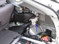
The unmodified wiring
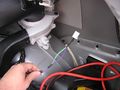
Unplugged and rubber casing stripped back
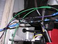
Ladder of diodes
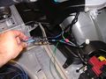
Finished wiring modification


Alternative 2 (does not cut Prius wires, but is expensive): Buy two each of the following Toyota replacement OEM battery plug and mating pins:
   OEM battery fan plug pins:  Toyota P/N 82998-12380
   OEM battery fan plug mating pins:  Toyota P/N 82998-12370
Splice one plug pin, a mating pin, and a green wire together. Splice a black wire to a plug pin, and a violet wire to a mating pin. Splice the three 1N5402 diodes between the violet and black wires as described above. Now remove the pin with the light green wires from the OEM battery fan plug, connect it to the mating pin with the green wire attached, and secure with heat-shrink tubing. Insert the plug pin attached to the green wire into the OEM battery fan plug. Next, remove the pin with the violet wires from the OEM battery plug and connect it to the mating pin with the violet wire attached, again securing it with heat-shrink tubing. Insert the plug pin attached to the black wire into the OEM battery fan plug. The pins are removed one at a time so that there is no possibility of getting them reversed when inserting the new pins. As above, the other end of all three wires are routed to the control board, where they are attached to J8F as per the diagram.
The pins can be removed from the OEM battery fan plug by inserting a tiny screwdriver from the back to push the plastic catch aside while pulling on the wire attached to the pin.
CAN-View & EV Mode button
Overview
Start by installing CAN-View. CAN-View gives you insight into how the Prius works and it is best to have it installed before doing the conversion. Please see PriusPlus-Theory for more information on what CAN-View and Prius EV Mode Button do and how they work.
You will need to purchase CAN-View from hybridinterfaces.ca. There are currently 4 versions of CAN-View available. Version 3 and 3plus require an '04 or '05 Prius and makes use of the built in display (or MFD) while Version 4 and 4plus work with an 04-07 Prius but requires an external touchscreen (since the built in touchscreens were changed in the '06 model and are no longer compatible.) Version 4 has the PHEV relays built onto the main board, while version 3 has an extra optional PHEV relay board, which is required for this conversion. Version 3plus and 4plus feature a smart relay board which can interact with battery regulators. At the present, the PriusPlus conversion method does not make use of the smart relay board.
Installation
Approx. time requirement: 45 minutes - 2 hours
The CAN-View is installed differently depending on whether or not your car is equipped with in-dash navigation. Detailed instructions with photos are available with NAV or without NAV. It is best to install and route the wires for the Prius EV Mode Button at the same time since they both require disassembling the dash.
ToDo the following section is shared with the PiPrius conversion process#CAN-View .26 EV Mode Button documentation. Any changes should be generic enough to satisfy both, place project specific notes above or below it. Another set of instructions may be needed for the CAN-View Version 4 which does not integrate with the OEM MFD and gets power directly from the OBDII port, Prius CAN View V4 Mounting options at PriusChat.com covers various ways of mounting the second touch screen.
Installing the CAN-View Version 3 and Prius EV Mode Button both involve disassembling the same areas of the Prius so will be covered here at the same time. You should also be familiar with these cv#reference materials.
- cv1. File:Stereo Accessory Install Guide 04 Prius v1.03.pdf from http://www.chrisdragon.com
- cv2. File:PriusXMradio3.2.pdf from https://www.metrotpn.com
- cv3. File:CAN-View installNONAVwt.pdf Adapted from http://www.hybridinterfaces.ca/installNONAV.html
- cv4. File:CAN-View installWNAVwt.pdf Adapted from http://www.hybridinterfaces.ca/installWNAV.html
- cv5. File:Prius-evbutton-install.pdf from http://www.calcars.org/prius-evbutton-install.pdf
- cv6. File:FactoryEV.pdf from http://www.scubadivervideo.com/Files/factoryEV.pdf
We begin by disassembling the dashboard. cv1 cv2
- Remove the bottom cover of steering column
- Releasing the steering wheel adjustment handle and removing the silver screw.
- Turn steering wheel 90 degrees to right and left to remove black screws on each side.
- Remove the lower cover by carefully pulling down on lower half.
- Disconnect the headlamp flasher plug on left side of steering column.
- Remove plugs cover by unlocking two side tabs/clips.
- Remove 3 unused connector pins using a jeweler's screwdriver to disengage and slide them out.
- Optionally to use the headlamp flasher circuit as an EV Mode button:
- Solder some length?? of black wire to a new pin and use it to replace:
The Red(#11-B10) wire to preserve day time flashing function, will disable night time flashing.It has been discovered that this does not work properly as the red wire is used for both the high beam and flash functions when the lights are turned on, thus disabling high beams at night. Anyone who has implemented this option should reinstall the red wire, moving the ev-mode button wire to the violet wires location instead.- The Violet(#17-B4) wire to preserve night time flashing function, will disable day time flashing.
- Route new black wire along existing bundle then towards center console to later meet up with OBDII cable.
- Snap the cover back onto the flasher plug and reinsert into switch.
- Reassemble steering column, be sure everything is aligned properly.
- Remove lower glove box by squeezing the inside sides together to lower box below catches, then unclip the small piston from right side. Lower box until the lower joints detach from dash, remove pneumatic cylinder noting it's orientation.
- Remove passenger side silver air vent cover by pulling out from the bottom first. Next remove the small interior colored piece just below the vent piece by pulling straight out.
- If installing CAN-View Without Navigation: cv3
- Remove drivers side air vent cover, press down and pull out on top.
- Remove lower center console hump with 12v lighter power socket, remove barb from passenger side, pull out.
- Remove air vent at right side of MFD screen, open upper glove box to pull out vent.
- Remove lower drivers side interior colored dash panel, one black screw above hood release, one exposed behind drivers side vent.
- Remove black lower dash key fob panel, leave hanging with wires connected.
- Remove upper drivers side dash panel with power button, leave wires attached.
- Remove air vent at left side of MFD screen, the shift lever with remain in place, detach and slide park button forward through silver panel to expose and detach cable, then remove the panel and reattach the park button to it's cable to prevent errors during later tests.
- Remove 10mm bolts, one on each side of MFD screen, pull screen out sharply and rotate towards drivers side.
- Tap grey OEM wire for 12v power, top row 2nd from the left.
- Attach CAN-View video cable to MFD and power spade to tapped grey wire, run cable out directly behind screen.
- Connect CAN-View OBDII cable to OBDII port and route cable behind center console towards glove box along with headlamp flasher ev-mode button wire if installed.
- Test CAN-View, then reassemble center and drivers side of dash.
- CAN-View will be mounted under passenger seat, above JBL amplifier if present.
- If installing CAN-View With Navigation: cv4
- Route OBDII Cable around foot well and down drivers side door sill to underneath drivers seat. Route headlamp flasher ev-mode button wire if installed behind center console and glove box.
- Tap grey OEM wire from navigation unit for 12v power.
- Connect CAN-View video cables to navigation unit.
- Test and attach above and to rear of navigation unit.
- Solder new pin to some length?? of black wire, and optionally the black wire which connects to the headlamp flasher.
- Install pin with black wire(s) to ev-mode button location in HV ECU H14#27. cv5 cv6
- The HV ECU is the one closest the exterior of the car with grey plugs.
- H14 is the lowest of the four connectors.
- Pin #27 is located on the most interior (broken into three segments) row, the second from the bottom left corner, in the only open location between two red wires.
- Using a jeweler's screwdriver raise the white terminal retainer, fully insert the new pin, re-compress the retainer, and plug terminal back into HV ECU.
- Route black EV Mode wire, and OBDII & Video if non-NAV, along passenger side door trim exiting under carpet before pillar to the hole in carpet below passenger seat and to relay cable.
- Route relay cable from CAN-View under rear passenger side door trim towards rear of car.
- Reassemble passenger side of dash and door trim.
Finally, Connect all the cables to CAN-View.
Configuration
- Configure CAN-View
ToDo
Troubleshooting
References
<references/>