|
General Disclaimer: (HV) (DC) injury or death hazard, use at your own risk, may void warranty. |
PriusPlus-Mechanical
| Click show for a short list of the current PHEV conversion and kit options for the Toyota Prius. |
|---|
|
For Prius conversion details see the Prius PHEV article and comparisons table.
|
|
--={ Project Overview
}={ 2007 Maker Faire
}={ Theory
}={ Instructions
}={ Parts List
}={ RawData
}={ Latest News
}=--
|
|---|
|
--={ Historic }={ Battery }={ Schematics }={ PseudoCode }={ Photos }=-- |
 Team Photo from the PriusPlus conversion of Sven's Prius from Nov 2006. This is the home of the PRIUS+ PHEV DIY (Do-it-Yourself) documentation. These pages are currently anonymously editable, which may change in the future. Please feel free to use the Discussion page for general discussion and commentary on the main article. If you would like to add to an existing section use the "edit" link near that topic's heading. Don't forget to use the Summary field to describe your changes. While editing use the "Show Preview" button to make sure your changes look like you expect them to, before you click "Save Page". |
Intro Paragraph here maybe with a link to the main PriusPlus article, links to external sites can appear as formatted CalCars, just plain URLs like http://www.calcars.org, or fancy references such as that in the next paragraph.
Another Paragraph and such, you can get help at our Help:Contents#How do I use the Wiki Website page <ref>http://en.wikipedia.org/wiki/Help:Contents more help using the wiki.</ref> Feel free to simply remove this, or if you like move all of this example text to the page's discussion article.
Contents
- 1 Mechanical Sub Parts Construction
- 2 Disassembling the Prius
- 3 Installation of parts into Prius
- 4 References
Mechanical Sub Parts Construction
Battery Trays
Approx. Time Requirement: 10-12 hours
Tools needed
- Metal Drill Bits: 3/32, 1/8, 5/32, 7/32
- Hacksaw with metal blade (or other method of cutting 1/8 inch aluminum)
- Drill or Dremmel
- Drill or Dremmel press recommended
- Metal file for filing rough edges.
- Wood saw
- Pop riviting tool
- Grinder (either an attachment for Dremel or bench grinder)
Parts needed
- Aluminum material
- Either 3/4" or 1" by 1/8" thick aluminum angle iron (2x 8 foot sections, 1x 4 foot section)
- 1/4" Aluminum channel iron (1x 8 foot section, 1x 4 foot section)
- 32 5/32 thick, 1/4 inch grip pop rivits
- 32 #4 flat head self threading screws at least 1/2 inch long
- Small piece of plywood for making jig (optional, but makes things easier.)
- Small pieces of wood for making jig (optional)
- Wood screws (optional)
Assembly Steps
- Cut 4 sections of the 1/4" aluminum channel iron to the exact length of the batteries (should be 7 1/16 inches.) Having the batteries actually present is important for measuring. A total of 16 of these peices will be required for all 4 trays.
- Lay out 5 batteries and put the 1/4" aluminum channel irons between the batteries. Measure out the length and cut 2 sections of the aluminum angle irons to the length of the batteries (should be 16 5/16 inches.) A total of 8 of these sections will be required for all 4 trays. See photos below for how to layout the pack.
- Layout 5 batteries with the angle irons from above and measure the width and cut the 2 end peices (should be 7 1/4 inches.) A total of 8 of these peices will be required for all 4.
- Lay everything out on top of a peice of plywood and double check measurements with batteries set in the tray as shown below. It is important that the end peices are under the peices that run along the length of the tray.
- Screw down blocks of wood around outside of the frame as shown to hold the outside angle irons exactly where they are.
- Remove the batteries one by one and put in pieces of wood where the batteries were to hold frame and aluminum channel irons in place. This jig will hold all the pieces together while drilling.
- Using a small drill press or preferably a Dremmel drill press, drill 2 3/32" holes into each corner (or probably only one if using 3/4" angle irons.)
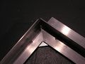
- Once the holes are drilled, remove the top angle iron (the 16 5/16 inch one) and using a 1/8" drill bit, widen the holes so that the #4 screws can pass through them freely (only do this on the longer angle iron, not the bottom!) Then counter-sink with a 7/32" drill bit so that the screw will sit flush in the aluminum (see photo below.)
- Put in #4 self threading screws. The screws should grab into the smaller angle iron and hold the angle irons together firmly. The screws will stick out the other side.
- Using a cutoff attachment on a Dremmel (or a hacksaw, but Dremmel works much better), cut the screws off. Then grind them down flat using the cut off attachment on a Dremmel or a bench grinder.
- Re-insert the finished angle iron frame into jig, and place channel irons in place. Drill 5/32" holes at each end.
- Using a pop-riviting tool, insert 5/32" aluminum rivits into the channel irons from the bottom and tighten.
- Repeat 3 more times for a total of 4 trays.
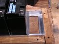
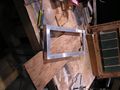
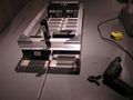
Photos
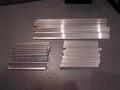
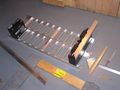
All necessary cut aluminum pieces for 4 trays
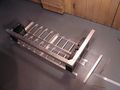
Tray set together with batteries
Tray parts laid out
Place wood around tray frame
Inserting wood blocks to hold aluminum
Inserting wood blocks to hold aluminum
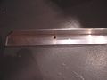
Holes drilled in aluminum
Finished corner with screws in
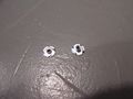
Shows the self threading screws sticking out
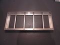
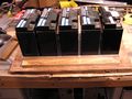
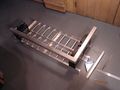
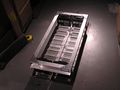
The finished tray
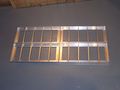
All 4 finished trays laid out like they will be


Battery Box Supports (Classic Method)
Approx. Time Requirement:
Tools Needed
- Chopsaw with metal cutoff blade (hacksaw or jig saw will also work)
Parts Needed
- 1 1/2 inch by 1/8 inch thick aluminum angle iron (2x 8 foot sections)
- 1 1/2 inch by 1/8 inch thick aluminum strip (1x 4 foot section) (optional for extra strength)
- 2 3 foot long 1/2 inch or 3/4 inch steel tubes.
- Screws, Nuts, Lockwashers, Bolts
Assembly Steps
- Cut 4 aluminum angle irons 38 inches long and layout so that 2 trays sit into each pair (see photos) (Todo: Length may be slightly long, you will probably need to adjust the length when mounting!)
- Optionally cut the aluminum strip to the same length as the angle irons and set vertically in the middle of the assembly. This strip would then be bolted horizontally with the 2 center angle irons in the center and on each side. The idea is to reduce bounce in the center (weakest part) of the battery pack when going over bumps.
- Cut the steel tubes to the appropriate length (Todo Get exact length)
- Lay everything out as shown in the first photo and use the battery trays to determine the spacing. Leave enough space between the trays for a 1/4" nut.
- Mark the locations where the aluminum angles sit on the steel tube and drill holes.
- Drill holes in the opposite side of the steel tube, big enough to fit the head of a bolt through
- Drill 2 additional holes in each steel tube in the middle of where each tray will sit. Again, drill out the other side so a nut can be fit through it. Then put a threaded 5/8" threaded rod through the hole and put a nut on each side (and a lockwasher on one side.) This will serve as the holddown for the battery box top.
- Drill 4 holes through the tube, evenly spaced over the entire length. These holes are for mounting the battery box frame to the car.
- Drill additional holes as needed to support the electronics tray
- Once holes are all drilled, coat the steel tube with anti-rust paint / spraypaint.
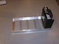
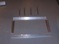
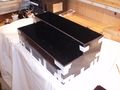
Photos
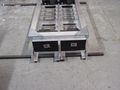
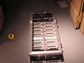
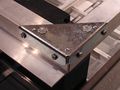
The completed battery box sitting on steel tubes (unattached)
Shows how the box sits on the aluminum angle supports. Also includes optional 1 1/2 inch aluminum strip in center.
During construction, shows supports without optional strip in center.


Battery Box Supports (Alternative Method)

Approx. Time Requirement: 4-7 hours
Tools Needed
- Chopsaw with metal cutoff blade (hacksaw or jig saw will also work)
- Bench grinder
Parts Needed
- 1 1/2 inch by 1/8 inch thick aluminum angle iron (2x 8 foot sections)
- 1 1/2 inch by 1/8 inch thick aluminum strip (1x 4 foot section) (optional for extra strength)
- 16 inches of steel 1 1/2 inch angle iron
- 2 joist hangers for electrical conduit
- Screws, Nuts, Lockwashers, Bolts
- 1/4" nuts
- 1/4" or 1/8" rubber pads (optional, but required if heating pads are to be installed.)
- anti-rust paint or spraypaint
Assembly Steps
The center strip
- See the diagram to the right to see how everything assembles.
- Cut 4 aluminum angle irons 38 inches long and layout so that 2 trays sit into each pair (see photos) (Todo: Length is too long, you will need to adjust the length when mounting, so be careful drilling holes, test fit first!)
- Optionally cut the aluminum strip to the same length as the angle irons and set vertically in the middle of the assembly (for strength). This strip would then be bolted horizontally with the 2 center angle irons in the center and on each side. The idea is to reduce bounce in the center (weakest part) of the battery pack when going over bumps.
- Lay out 2 aluminum angles so they form a "T" with the top of the "T" being on the floor. Optionaly insert the aluminum strip into the middle
- Lay everything out as shown in the first photo and use the battery trays to determine the spacing. Leave enough space between the trays in the middle for a 1/4" nut.
- Drill holes through each end of the assembly to anchor the two angles (and optionally the strip) together. The holes must be outside where the battery trays will sit (remember to leave space for a 1/4" nut (which is larger than 1/4")
- Optionally, cut rubber pads to go under each of the aluminum angles.
- Other holes will need to be drilled later when ready to mount.
Steel Angle Iron Brackets
- Cut 4 sections of steel angle iron about 1 to 1 1/2 inches long
- Drill a 3/8" hole in the center on one side of the angle iron.
- On the inside of the angle iron, weld (or use JB weld or another strong epoxy) a 5/8" nut on the inside so a bolt can go through the angle iron and into the nut
- Drill a 5/8" hole in the center of the other side of the angle iron
- Paint the steel with a clean metal anti-rust primer (then allow to dry)
- Spray or paint the primed steel with anti-rust paint
Steel Supports
- Cut 2 sections of steel angle iron about 4 inches long each
- Drill 2 5/8" holes in the bottom of the angle iron
- These will be used later for mounting into the Prius - the rest of the assembly must be done later
Todo This isn't finished - check the diagram for more details
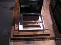
Photos
Shows how the box sits on the aluminum angle supports. Also includes optional 1 1/2 inch aluminum strip in center.
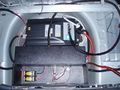
Test fitting in the Prius
Support Steel mounted
Shows the optional rubber pads
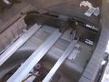
Detailed photo of the right side
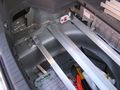
Detailed photo of the left side
With the battery trays in


Battery Box Top
Approx. Time Requirement: 10 hours
Tools needed
- Metal Drill Bits:
- Chopsaw with metal cutoff blade very helpful (must be capable of 45 degree angles.)
- Tablesaw with Plexiglass blade, or other method of cutting Plexiglass
- Drill
- Metal file for filing rough edges.
- Dremmel
- Cutoff attachment for Dremmel
Parts Needed
- Aluminum material
- 1 1/2 inch by 1/8 thick aluminum angle iron (2x 8 foot sections)
- 1 inch by 1/8 inch thick aluminum angle iron (1x 4 foot sections for classic - 8 feet for the alternative mounting method)
- Corner brackets - can be found at Mennards in shelving hardware section
- 24x #8-32 flat head machine screws
- 16x #8-32 nuts
- 8x #8-32 x 1/4 inch binding posts
- 1/4 inch Plexiglass or (preferably) Lexan sheet, at least 33 inches by 18.5 inches.
- 4 small non-conductive nylon screw and binding posts (for holding Plexiglass "shields")
Assembly Steps
(These steps may not be completely accurate to the CalCars official method)
- Cut 2 strips of Plexiglass (or Lexan) 32.5 inches by 1.5 inches. These peices will act as a sheild between the battery terminals and the aluminum (to prevent shorts.)
- Cut opposing 45 degree angle at the end of 2 of the 1 1/2 inch aluminum angle iron peices to form one of the corners.
- Layout the four trays in the frame angle irons (important for getting correct measurements.)
- Place 4 batteries in the trays, one in each corner (see photo.)
- Place electrical tape over the terminals on the batteries to help prevent any arcs.
- Make sure to leave space for the middle bolt down and bolts for the frame. (The battery box base isn't finished yet and requires space in the middle.)
- Set one of the cut angle irons on top of the batteries (be sure not to arc the batteries!) Place the Plexiglass "Shield" in place and use clamps to it there. This allows for accurate measurements.
- Lay the other angle iron with the opposing 45 degree angle out and measure the width & cut with a 45 degree angle (end peice should be about 15 3/8 inches wide.)
- Hold the angle iron that will be used to bolt down the top to the end of the battery pack (use clamps to hold it on.) For the classic mounting method, this is only required on the left and right sides. For the alternative mouting method, the angles should go around the entire battery box top.
- Holding the angle irons and bolt down angle iron right where they should be, set the corner bracket on the corner and make sure that it covers the angle iron that will be used to bolt down the battery box.
- Mark where the holes on the top of the bracket are on the angle iron (or drill holes if necessary.)
- Using the Dremmel cutoff tool, cut down the binding post so that it does not stick all the way thought the bracket if set on top (see picture.)
- Drill a hole in the angle iron and countersink it so that the #8 flat top machine screw fits flush. Put screw in and repeate for the other angle iron.
- Repeate for other sides cutting the angle irons to the right lengths. The length of the angle iron on the side of the battery box should be 34 inches.
- To strengthen the structure of the top, drill holes in from the sides, countersink from the inside and bolt using #8 flat head screws and nuts (bolting the top down is important, remember that the top must hold weight if the car goes over large bumps or is involved in an accident or rollover.)
- Using a drill press or drill, drill through the Plexiglass on the side and the aluminum angle irons near the edges. Countersink the hole in the Plexiglass and insert non-conductive nylon screws and binding posts to hold Plexiglass in place.
- Using the Dremmel with cutoff attachment, grind off the bolts that are sticking out.
- Cut the Plexiglass sheet to the correct length and width to fit snuggly into the top of the battery box.
- Holes need to be drilled into the bolt down angle irons on each side, but I don't have those measurements and it depends how it is bolted down. Holes also need to be drilled in the middle on each aluminum angle iron to clamp down the top to the bottom of the battery box for extra strength.
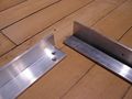
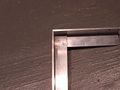
Photos
Starting on the top of the battery box
45 degree angles cut in angle irons
Corner bracket just set on the top
3 angle irons cut and just sitting on the box
Shows the Plexiglass "shield" on the inside of the angle irons
Partially assembled battery box - bolted on top, but not the sides
Inside of the corner of the battery box top
Binding posts that I choose to use. They worked, but they aren't part of the official conversion method
A completed corner, bolts in and have been ground off.
Shows the angle iron that will be used to bolt down the top
Mostly finished battery box. Still lacking the bolts in the center of the pack, holes for bolting the top down and holes in the frame


Tips
- If you are buying a new metal cutoff blade for an existing chopsaw, make sure to get one that is large enough to actually cut all the way through the metal with your specific chopsaw.
- Aluminum blades with small teeth do not seem to work well for cutting through 1/8 aluminum angle irons! They grab and tend to throw the saw and are almost impossible to control. Don't attempt an aluminum cutting blade with teeth on a radial saw!
- A hacksaw can work in place of the metal cutoff blade, however it is much more difficult to get straight cuts, even with a metal guide for the hacksaw.
- A jig saw seems to work well for cutting the aluminum angle irons
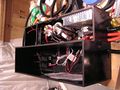
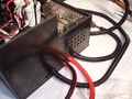
Electronics Tray (Classic Method)

The electronics tray

Electronics Box (Alternative)

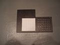
Starting with the materials
The electronics box taped together
Components being mounted
Partly populated electronics box
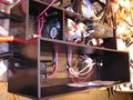
Partly populated electronics box
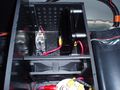
Close up of the diode
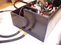
Left outside of electronics box
Right outside of the electronics box
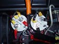
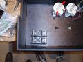
Close up of the mounted contactors
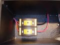
Close up of the mounted fuses
The electronics box with the HV section's cover resting on top


Disassembling the Prius
Battery Carpet & Seat Removal


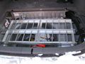
Remove the two bolts holding down the carpeting over the OEM battery. Be sure to keep them in a plastic bag so they do not get lost. Then lift up on the Velcro attaching to the rear seats. Then, simply pull straight up on the carpeting assembly. It will snap out and expose the top of the OEM battery. There are 2 carpeting clips that must be removed to fully remove the cover from the OEM battery.
With the OEM battery carpeting removed (or the Velcro simply pulled up), remove the two bolts holding in the seat. The seat back then comes out giving access to the front side of the OEM battery (needed for the OEM tie-in.)
Side panel Removal
Both of the carpeted side panels in the rear of the Prius must be removed. The driver's side panel must be removed to access the OEM battery for tie-in, and the passenger's side must be removed to access the OEM battery fan to add the override wiring.
- Remove the screen from the trunk (if it hasn't been already.)
- Remove the cover from the driver's side storage cubby hole (if it hasn't been already.)
- Remove the black strip in the very rear of the trunk (where the latch is for the trunk) by simply lifting straight up (it will pop out.)
- Remove the arm rest sections on the outside of the seats (Todo - add photos)
- Remove the 10mm bolt inside the screen holder using a ratchet with an extension
- Remove the 10mm bolt in the back of the side panel in the section which holds the screen if were deployed. This can be done with a 10mm ratchet or a screwdriver.
- Pull straight out on the entire assembly.
- On the drivers side, there is a wire which connects to the trunk lamp which needs to be disconnected.
- Repeat instructions for the passenger's side.
Installation of parts into Prius
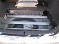
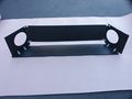
Air Vents (Classic Method)
Remove spare tire and the two black drain plugs that sit in the tire well. You may have to use a dremmel to open the hole so you can drop in the [Delete later-(Ron I think I found a piece of conduit that will flush mount in here. The PVC pipe can be glued to it. I’ll get you a part number and picture. By doing this a project could be prepped weeks in advance and the spare will still fit in there until the final conversion days.) ] 2” PVC threaded coupling. Next connect the 2” 90 deg. Elbow and then a length of 2” PVC pipe per this photo (add photo showing underside of car with both pipes pointing back to the rear.)
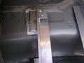
Battery Box Foundation
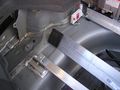
Line up the battery box supports where they should go and drill holes into the trunk floor. It may be necessary to remove part or all of the heat shielding from the muffler on the underside of the car to find the holes. Bolt down.
(Todo Need to detail removing the heat shield on the underside of the car.) To remove the plastic shield on the driver's side rear of the car, use a flat screw driver to pop out the 3 fasteners. On the back of the shield there is a 10mm bolt holding the plastic shield in place which also needs to be removed.
Electronics Tray
Charger
Bumper Mounted Inlet
This is an optional replacement for the mounted cord reel. There may be other inlets available, but a Marinco 150CCI works well and costs about $25-$30.
- Remove the plastic shield on the driver's side of the car if it hasn't been already (see above for instructions.)
- Using a circular drill bit with starting drill bit, drill a 1 7/8" hole in the bumper where you want the inlet to be mounted.
- Route the cable to the inlet before installing the inlet.
- Fasten the inlet to the bumper
References
<references/>