|
General Disclaimer: (HV) (DC) injury or death hazard, use at your own risk, may void warranty. |
PriusPlus History
| Click show for a short list of the current PHEV conversion and kit options for the Toyota Prius. |
|---|
|
For Prius conversion details see the Prius PHEV article and comparisons table.
|
|
--={ Project Overview
}={ 2007 Maker Faire
}={ Theory
}={ Instructions
}={ Parts List
}={ RawData
}={ Latest News
}=--
|
|---|
|
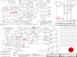
--={ Historic }={ Battery }={ Schematics }={ PseudoCode }={ Photos }=-- |
 Team Photo from the PriusPlus conversion of Sven's Prius from Nov 2006. This is the home of the PRIUS+ PHEV DIY (Do-it-Yourself) documentation. These pages are currently anonymously editable, which may change in the future. Please feel free to use the Discussion page for general discussion and commentary on the main article. If you would like to add to an existing section use the "edit" link near that topic's heading. Don't forget to use the Summary field to describe your changes. While editing use the "Show Preview" button to make sure your changes look like you expect them to, before you click "Save Page". |
|
This item is out of date but kept for posterity sake, |
See Also:
Prius PHEV Prius+ Documentation(.doc) Notes and Instructions
|
|
Ron Gremban, 1/18/2006
© 2006 by ForSites Corp.
Permission granted for private use as long as the following is recognized: This circuitry is experimental. Its use may void Toyota warranties, It could possibly damage the vehicle or make it drive erratically. Due to lethal high voltages involved, all due safety precautions must be taken to protect oneself and anyone who comes near the vehicle. You MUST have experience with high voltage safety precautions!
Note: this modification can add 200-300 lb extra weight in the rear of the vehicle, depending on the specific battery pack used and whether or not the OEM battery is removed. This will use up some of the Prius’ available rear axle useful load. In practice, my PRIUS+’s handling has been fine, though it rides a little low in the rear. I recommend avoiding simultaneously carrying rear passengers and significant load in the cargo area.
History
I was the technical lead for CalCars’ 2004 PRIUS+ modification of my 2004 Prius into a pluggable hybrid (PHEV), and remain CalCars' technical lead. Felix Kramer, CalCars’ founder, enlisted me in mid-2004, shortly after I first contacted him. The project had a lot of internet collaboration as well as physical volunteer help, largely from Electric Automobile Association (EAA) members (thanks to everyone). You can view much of the history of the project at http://autos.groups.yahoo.com/group/priusplus/messages, especially the summary at http://autos.groups.yahoo.com/group/priusplus/message/421. (This group is currently closed to new members, but postings are viewable by non-members.).
Our first attempt to interface more battery capacity to Toyota’s hybrid system (not unexpectedly) didn’t work. We discovered that Toyota’s (Battery ECU) battery management computer uses Amp-hour integration as its major way of determining battery state-of-charge (SOC). Therefore, just as with the OEM battery, after a mile or so, it would pop the vehicle out of EV-only mode due to a very low SOC indication (in spite of the new battery’s much larger capacity and high actual SOC).
Greg Hanssen offered EnergyCS’ help at low cost. They had a CAN bus controller that they turned into a battery management computer to replace Toyota’s Battery ECU by emulating that OEM computer’s CAN messages to the rest of the hybrid system. This system, though proprietary, got our PRIUS+ working quickly; first smoke-tested in late September, it was working well by early November 2004.
Greg and others at EnergyCS then got excited, built their own Prius conversion using Valence Li-ion batteries, and – with CleanTech, a company to which Felix introduced them – started EDrive Systems to commercialize Prius PHEV conversions. This is an exciting development, which may provide, for most people, the first opportunity to own a PHEV.
However, there is also a community of experimenters, schools, and others interested in doing such modifications themselves, and the EnergyCS controller is not available for this purpose. Fortunately, Dan Kroushl discovered and shared the information that a higher-voltage battery is capable of fooling Toyota’s Battery ECU into giving a higher SOC reading. I started experimenting with higher voltages of PbA batteries and came up with an algorithm for fooling the Battery ECU in an organized way. I tried it first with PbA batteries, and only with manual control, but I expected it to work more generally. It will be described in detail below.
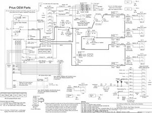
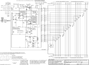
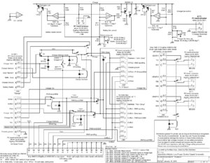
I have now completed (3) schematic diagrams for a PRIUS+ conversion using this technique, and am working on software to automate the control as well as display and record relevant vehicle information. This is intended to run first on a laptop computer, then on a PocketPC PDA that can be semi-permanently mounted (and left running) in the car.
Battery Pack
I specified a BB Battery PbA battery pack (18 EVP20-12B1 modules from ElectricRider.com) for our first conversion attempt, in order to go through our learning curve with inexpensive, fairly indestructible batteries. This turned out to be an excellent decision, as, though it required replacement after 200 cycles and just under a year, this pack has sustained our PRIUS+ through over a year of work on finding a more advanced battery pack. The BB electric bicycle batteries, though very marginal for this application, are actually quite remarkable among PbA batteries. When fully charged, these 20Ah (12Ah @ ½ hour rate) batteries have a lower internal resistance (~250 milliohms) than the OEM battery (300-350 milliohms) and are capable of supplying the Prius’s maximum draw of 200A – a 10C or 17C rate, depending on which capacity you calculate it against. At low SOC, however, the internal resistance is >500 milliohms, too high for full hybrid functionality. My PRIUS+’s performance has been documented in CalCars’ PRIUS+ Fact Sheet. In short, the BB Batteries weigh about 260 lb and provide for approximately double the normal Prius’ gasoline mileage for around 20 miles of Mixed-mode (town and highway) driving on each charge.
Next, we planned on installing an NiMH pack, largely to prove that the chemistry that is already in all of today’s mass produced hybrids is also capable of powering electrically and economically effective PHEVs; thereby removing one more auto company excuse for not building them. As soon as we have the people-resources, we will move on to work with one or more of th newer high-performance Li-ion suppliers, which we expect to require additional engineering work to ensure proper cell-by-cell charge and discharge control as well as to engineer out any likelihood of thermal runaway problems, to which this chemistry is prone.
I spent the first nine months of 2005 looking for NiMH and/or Li-ion batteries that fit the PRIUS+ requirements. In the process, I learned a lot about the characteristics of these advanced battery chemistries. For example, special problems are encountered when NiMH cells or strings are put in parallel. This should only be done with full strings, and with special control electronics such as that designed for the Electro Energy pack (below). Wayne Brown and Dan Kroushl are using many parallel strings of NiMH sub-C cells in their enhanced (but not PHEV) Prii. These small (3-3.6Ah) cells have good high power capabilities, and the parallel strings work well in their application where the cells do not get fully charged. I figured that D cells, also quite available, would require few enough parallel strings that the electronics might not be overwhelming. However, though many looked good on paper, all D cells I tested had at least double the expected internal resistance. Fortunately, Electro Energy came along with their specialized and capable NiMH batteries (below).
I also looked at many Li-ion possibilities. The least expensive option is currently 18650 cells, produced in huge volumes for laptop computers. However, these, like the sub-C NiMH cells, are very small (2-2.8Ah). Also, they are typically designed for 2-5 hour discharge rates and lack high power capabilities. One pays more for high power, low susceptibility to thermal runaway, and long cycle life – and you still have to parallel many cells to reach the necessary capacity. A typical PRIUS+ pack would use at least 1200 cells, providing plenty of failure points. While looking only at technologies that are in production, if only in the early stages, CalCars has begun discussions with specialty Li-ion manufacturers with lines of high-power-capable Li-ion cells.
CalCars and Electro Energy, Inc, in Danbury, Connecticut, are now in the late stages of a joint project to adapt their unique form of NiMH packs to the PRIUS+. As part of the project, I have designed control circuitry that is specific to the characteristics of this battery as well as Toyota’s BMS. When complete (expected yet this first quarter of 2006), the pack should weigh about the same as the BB Battery pack but last for 40-50 miles of Mixed-mode driving. Internal resistance figures we have seen so far are in the 200 milliohms range. It is possible that Electro Energy will elect to sell this pack to experimenters, so stay tuned.
Several EAA members have recommended Hawker PbA batteries which don’t appear to exist any more under that moniker. However, I believe I just tracked down their descendents: Odyssey batteries by EnerSys Inc. They have a model PC625 that may be less marginal than the EVP20 and thereby useful for experimenters’ PRIUS+ conversions. I don’t yet know price of availability. Though rated at 16Ah, they have the same rated ½ hour capacity as the EVP20, are 1 lb lighter, and have a claimed 1800A short circuit current at full charge, requiring an internal resistance of less than 7 milliohms (126 milliohms for a full pack of 18). Also, they claim an 80% DOD cycle life of 500 and the ability to withstand long periods of discharge with little damage.
Several PRIUS+ battery pack specifications are provided in Appendix A.
High Voltage Circuit
The high voltage circuit consists largely of the PHEV battery pack, some contactors, a circuit to emulate the OEM battery’s taps, a charger, and miscellaneous battery support devices. The OEM battery is not in the circuit and can be removed to reduce the vehicle’s weight by nearly 100 lbs. However, the circuitry is designed to make reconnecting the OEM battery easy, and it is recommended that it be kept in the vehicle until your conversion’s reliability has been proven to your satisfaction.
For safety and ease of installation/removal, the battery pack has been divided into two banks, separately fused and used in series but connected together only during operation. With the current BB battery pack, this corresponds to the two physical rows of battery modules. This arrangement should hopefully work for many other batteries as well, though the Electro Energy pack is specialized and requires very different high voltage and control electronics.
The color or high voltage wiring is shown as red/orange or black/orange, depending on polarity. This is because hybrid vehicles have standardized on orange to depict high voltage circuitry to service and emergency personnel, but it is desirable to indicate polarity as well. Though orange welding cable is not commonly available, the ends can be wrapped in orange tape or have orange tie wraps added. #6 welding cable should be sufficient for the high power cables. Anderson connectors have been specified for all high voltage connections, as both ends can be hot when disconnected. A Prius’ HV battery is electrically isolated from the vehicle’s chassis.
The charger to use will depend on the specifics of the battery pack. Choose one with the proper charge control and shutoff scheme for your specific pack. A 4kW, 3 hour Brusa NLG5 charger from MetricMind.com was used for our first conversion. A 1 to 1.5 kW capacity is usually sufficient and advantageous, as it is no problem for a PHEV to require all night to charge, and this capacity can be supplied from an ordinary U.S. 120VAC, 15A circuit. A charger with an electrically isolated output is highly recommended. The charger’s third-wire ground should be connected to the vehicle’s chassis, and it is recommended that the vehicle’s home charging circuit be GFI protected. Delta-Q is supplying chargers to EDrive Systems.
The charger also needs a 5A, 14-14.5V power supply capable of powering control electronics and fans, activating HVRL1, and supplying a trickle charge as well to the Prius’ accessory battery. The latter is because it has been found to be too easy to leave a dome light or other accessory on during charging, and it is inadvisable to deeply discharge the vehicle’s accessory battery. A 5A 12VDC supply is available for $30 from amondotech.com. I suspect it can be opened and modified (e.g. via adding three signal diodes in series with its zener diode) to put out 14VDC; I did this to a similar unit from Electronics Plus.
When the vehicle is off and not charging, HVRL1 is open, the PHEV battery is not connected to the hybrid system, and only half the 216V nominal voltage appears anywhere – still high and dangerous, but not nearly as much so as the full pack voltage.
Fuses F1 and F2, and F3 and F4, work in parallel to protect each battery bank from electrical system shorts. The parallel fuses were specified because fuses with high voltage DC ratings are rare and their fuse blocks are usually large with no insulation to protect from shorts and touching. These (page 15) Bussman LPJ-60SP fuses, in contrast, are rated for 300VDC and have small, page 237 insulated fuse blocks from which the fuses can be removed without touching live circuitry – but these fuse holders are available for fuses up to 60A, about half of the PRIUS+’s requirement, given the fuse’s particular speed of operation. It is therefore necessary in an installation using them to ensure that the wiring resistance through each fuse matches closely so as to as much as possible balance the current in the two fuses. An alternate fuse, not needing paralleling but harder to mount, is the page 33 – huge open fuseblocks for these shown on page 9 Bussman JJS-150, currently used in my PRIUS+.
During charge, the mid-pack contactor, HVRL1, is activated, but not the Toyota contactors SMRL1-3, thereby keeping the battery pack isolated from the hybrid system. The Toyota contactors are locked out whenever the vehicle is being charged (for details, see the control board description), keeping the battery pack isolated from the hybrid system.
When the Prius is running (READY light), all three contactors, HVRL1, SMRL2, and SMRL3, are activated, connecting the full pack voltage to the hybrid system. To reduce inrush currents, a precharger circuit is used. The stock hybrid system first connects the battery to the hybrid system through SMRL1, a resistor, and SMRL3. Then SMRL2 is activated and SMRL1 is deactivated.
Toyota-Related Controls
I have included, on and off the control board, circuitry to control battery cooling fans. These can be controlled via a computer using any criteria you choose. However, if you can redirect the OEM battery’s fan to your battery pack, it has the advantage of proportional control based on ambient and battery temperatures. You will need to replace Toyota’s battery thermisters with units mounted at strategic locations in thermal contact with your battery pack. You may need to fudge their values/range to relate your battery’s acceptable temperature range to that of the OEM battery, which is programmed into the Battery ECU. The NiMH voltage/temperature coefficient is probably also programmed in, and should be taken into consideration. In the right rear fender well is an exhaust port that can also be reused. If you use your own fan and control, it is recommended that air still be drawn from the passenger compartment and exhausted to the outside.
Note that operations at very low and very high temperatures have not yet been verified or planned for. In fact, my PRIUS+ needed to be switched back to its OEM battery pack before it would operate at all at freezing temperatures. There are potential issues of non-NiMH battery packs having different temperature coefficients than the Battery ECU is programmed for.
The Battery ECU uses voltage taps from the OEM battery pack to verify battery integrity and charge balancing. The 168-cell battery is thereby electrically divided into 14 12-cell subpacks (each subpack consists of two 6-cell prismatic modules). Even if your battery pack is similarly divisible, you will need to use a resistive divider like the Battery Tap Emulator Board to simulate these battery taps for the Battery ECU. Once the taps are emulated, the Battery ECU can be fed any voltage as its perceived battery voltage. Battery ECU SOC spoofing is done by raising this perceived voltage above the actual battery voltage. Once you have emulated the battery taps, you will need to provide as necessary for your battery pack’s charge balancing and actual SOC management. As this can be done in many ways for the many battery pack possibilities, it is outside the scope of this document.
Control Board
The control board (Low Power Control Schematic) provides the overall logic for a PRIUS+. It has a drive interlock and a charge interlock relay. The charge interlock relay can be jumpered to be energized whenever the charger is connected to the battery pack, or, if the charger is built-in and always connected, when the charger is powered. The charge interlock relay prevents driving while charging by disengaging HVRL1 and thereby disconnecting the two halves of the battery pack. The drive interlock relay energizes HVRL1 only when the vehicle is in READY mode.
TTL inputs to J3 control activation of EV-only mode, fans, and/or BMS spoofing via opto-isolators. An isolating power supply supplies 30V, an adjustable portion of which can be added to the battery voltage when necessary to provide BMS SOC spoofing. These TTL levels can be provided from a computer’s parallel port, independent of the computer’s power supply. Battery voltage is applied at HVJ6. Additional voltage, adjustable via R7, is added when RL2 is energized, and the resulting voltage is applied at J8, where the Battery Tap Emulator Board plugs in.
Battery ECU SOC Spoofing
Note: This is a work in progress. Spoofing requires monitoring the Battery ECU’s perceived SOC, available on the CAN bus. The idea is to keep the Battery ECU’s perceived SOC high (above 70%) until the battery pack’s real SOC reaches a value I will call normal hybrid SOC – the point where battery depletion (average discharge or PHEV mode) ceases and normal hybrid operation takes over. Normal hybrid SOC is determined by first deciding what you want to use as your battery pack’s deepest depth of discharge (DOD) during normal operations (the battery should only rarely be discharged further). This is a tradeoff, as a deeper DOD provides a longer EV range by making use of more of the battery’s capacity, but a shallower DOD gives the battery a longer cycle life. An 80% DOD (discharge to 20% SOC) is common. For the Prius, normal hybrid SOC needs to be about 1 Amp-hr (Ah) above maximum normal DOD; this is because the Prius’ hybrid system’s normal operations occur within about 1Ah either side of 60% (perceived) SOC. As an example, imaging my PRIUS+’s EVP20 battery pack has an effective capacity of 15Ah. 80% DOD would be at 20% (real) SOC, 3Ah up from full discharge or 12Ah below full charge. Normal hybrid SOC would then be 4Ah up from full discharge, 11Ah below full charge, or 4/15 = 27% (real) SOC. Start with a spoofing voltage of, say, 12V. The spoofing algorithm still requires some fine tuning, as it was developed with PbA batteries and no automation, but generally goes as follows:
When the battery is full and can accept little regenerative braking current, energize the added spoofing voltage whenever perceived SOC is 81% or lower, then remove the spoofing voltage whenever it reaches, say, 82%. As the perceived SOC may keep moving in the previous direction for a short time after a change (overshoot), you may find that to maintain >=80% SOC you have to switch the spoofing voltage ON at even higher than 81%.
Regenerative braking current is limited to around 20A whenever perceived SOC is 80% or higher. However, sometimes the engine races when SOC is set this high, or it becomes impossible to enter EV-only mode. If either of these things happen, reduce both SOC endpoints until it doesn’t anymore. If the engine starts racing, you can clear it by putting the car in Neutral, then back to Drive.
As long as perceived SOC is 70% or higher, the hybrid system tries to use up “excess” battery charge, so once the battery can accept regenerative braking, add spoofing voltage whenever perceived SOC is as low as 74%; remove it whenever perceived SOC reaches 78%. This allows for some overshoot as explained above. Change the endpoints as necessary to keep perceived SOC within the 70-79% range.
As the battery pack gets more and more discharged, at some point, perceived SOC will decrease below 70% even with the spoofing voltage turned on. At the point where the battery pack’s real SOC (usually determined by Ah integration) reaches its normal hybrid SOC (explained at the top of this section), perceived SOC, with spoofing voltage turned on, should reach 60% (the SOC that the hybrid system tries to maintain). If the battery pack has too much charge left (real SOC > normal hybrid SOC) when perceived SOC reaches 60% (with spoofing voltage turned on), adjust R7 to raise the spoofing voltage; if the battery pack has too little charge left (real SOC < normal hybrid SOC) when perceived SOC reaches 60% (with spoofing voltage turned on), adjust R7 to lower the spoofing voltage. Getting the right spoofing voltage may require many test runs, each starting with full batteries.
Well, this is it – all I can think of to say at this point. No doubt there will be confusion requiring further explanation, things that don’t work etc – and this document will be repeatedly revised, so watch out for the version number.
Best wishes, and, with all the high voltages, don’t forget to be safe instead of sorry. Among other things, always use insulated-handled tools and NEVER wear metal jewelry while working near the battery pack.
Appendix A: Battery Specifications
- Definitions:
- SOC == state of charge
Chemistry NeutralCalifornia Cars Initiative PRIUS+ Project
note * The values of these parameters should be maximized (or minimized, as appropriate), given a reasonable cost of doing so |
NiMHCalifornia Cars Initiative PRIUS+ Project
note: * The values of these parameters should be maximized (or minimized, as appropriate), given a reasonable cost of doing so |


