|
General Disclaimer: (HV) (DC) injury or death hazard, use at your own risk, may void warranty. |
PiPrius conversion process
| Click show for a short list of the current PHEV conversion and kit options for the Toyota Prius. |
|---|
|
For Prius conversion details see the Prius PHEV article and comparisons table.
|
|
--={ PiPrius
}={ Process
}={ fan control
}={ Manzanita Micro
}={ MM-PFC
}={ Mk 3 Reg
}=--
|
|---|
|
--={ More Vehicles: AVI }={ WhiteBird }={ GrayPearl }={ GreenCarCo }=-- |
 Team Photo from the PriusPlus conversion of Sven's Prius from Nov 2006.
|
These are the steps involved to convert a Toyota Prius into a PiPrius. There are a number of tasks to be completed in order for the entire system to function properly. Those tasks are covered in the following subsections of the Conversion Procedures. These instructions are currently under development and may not yet be complete.
References
<references/>
CAN-View Version3
Installing the CAN-View Version 3 and Prius EV Mode Button both involve disassembling the same areas of the Prius so will be covered here at the same time. You should also be familiar with these cv#reference materials.
- cv1. File:Stereo Accessory Install Guide 04 Prius v1.03.pdf from http://www.chrisdragon.com
- cv2. File:PriusXMradio3.2.pdf from https://www.metrotpn.com
- cv3. File:CAN-View installNONAVwt.pdf Adapted from http://www.hybridinterfaces.ca/installNONAV.html
- cv4. File:CAN-View installWNAVwt.pdf Adapted from http://www.hybridinterfaces.ca/installWNAV.html
- cv5. File:Prius-evbutton-install.pdf from http://www.calcars.org/prius-evbutton-install.pdf
- cv6. File:FactoryEV.pdf from http://www.scubadivervideo.com/Files/factoryEV.pdf
We begin by disassembling the dashboard. cv1 cv2
- Remove the bottom cover of steering column
- Releasing the steering wheel adjustment handle and removing the silver screw.
- Turn steering wheel 90 degrees to right and left to remove black screws on each side.
- Remove the lower cover by carefully pulling down on lower half.
- Disconnect the headlamp flasher plug on left side of steering column.
- Remove plugs cover by unlocking two side tabs/clips.
- Remove 3 unused connector pins using a jeweler's screwdriver to disengage and slide them out.
- Optionally to use the headlamp flasher circuit as an EV Mode button:
- Solder some length?? of black wire to a new pin and use it to replace:
The Red(#11-B10) wire to preserve day time flashing function, will disable night time flashing.It has been discovered that this does not work properly as the red wire is used for both the high beam and flash functions when the lights are turned on, thus disabling high beams at night. Anyone who has implemented this option should reinstall the red wire, moving the ev-mode button wire to the violet wires location instead.- The Violet(#17-B4) wire to preserve night time flashing function, will disable day time flashing.
- Route new black wire along existing bundle then towards center console to later meet up with OBDII cable.
- Snap the cover back onto the flasher plug and reinsert into switch.
- Reassemble steering column, be sure everything is aligned properly.
- Remove lower glove box by squeezing the inside sides together to lower box below catches, then unclip the small piston from right side. Lower box until the lower joints detach from dash, remove pneumatic cylinder noting it's orientation.
- Remove passenger side silver air vent cover by pulling out from the bottom first. Next remove the small interior colored piece just below the vent piece by pulling straight out.
- If installing CAN-View Without Navigation: cv3
- Remove drivers side air vent cover, press down and pull out on top.
- Remove lower center console hump with 12v lighter power socket, remove barb from passenger side, pull out.
- Remove air vent at right side of MFD screen, open upper glove box to pull out vent.
- Remove lower drivers side interior colored dash panel, one black screw above hood release, one exposed behind drivers side vent.
- Remove black lower dash key fob panel, leave hanging with wires connected.
- Remove upper drivers side dash panel with power button, leave wires attached.
- Remove air vent at left side of MFD screen, the shift lever with remain in place, detach and slide park button forward through silver panel to expose and detach cable, then remove the panel and reattach the park button to it's cable to prevent errors during later tests.
- Remove 10mm bolts, one on each side of MFD screen, pull screen out sharply and rotate towards drivers side.
- Tap grey OEM wire for 12v power, top row 2nd from the left.
- Attach CAN-View video cable to MFD and power spade to tapped grey wire, run cable out directly behind screen.
- Connect CAN-View OBDII cable to OBDII port and route cable behind center console towards glove box along with headlamp flasher ev-mode button wire if installed.
- Test CAN-View, then reassemble center and drivers side of dash.
- CAN-View will be mounted under passenger seat, above JBL amplifier if present.
- If installing CAN-View With Navigation: cv4
- Route OBDII Cable around foot well and down drivers side door sill to underneath drivers seat. Route headlamp flasher ev-mode button wire if installed behind center console and glove box.
- Tap grey OEM wire from navigation unit for 12v power.
- Connect CAN-View video cables to navigation unit.
- Test and attach above and to rear of navigation unit.
- Solder new pin to some length?? of black wire, and optionally the black wire which connects to the headlamp flasher.
- Install pin with black wire(s) to ev-mode button location in HV ECU H14#27. cv5 cv6
- The HV ECU is the one closest the exterior of the car with grey plugs.
- H14 is the lowest of the four connectors.
- Pin #27 is located on the most interior (broken into three segments) row, the second from the bottom left corner, in the only open location between two red wires.
- Using a jeweler's screwdriver raise the white terminal retainer, fully insert the new pin, re-compress the retainer, and plug terminal back into HV ECU.
- Route black EV Mode wire, and OBDII & Video if non-NAV, along passenger side door trim exiting under carpet before pillar to the hole in carpet below passenger seat and to relay cable.
- Route relay cable from CAN-View under rear passenger side door trim towards rear of car.
- Reassemble passenger side of dash and door trim.
Finally, Connect all the cables to CAN-View.
CAN-View Version4
Another set of instructions may be needed for the CAN-View Version 4 which does not integrate with the OEM MFD and gets power directly from the OBDII port, Prius CAN View V4 Mounting options at PriusChat.com covers various ways of mounting the second touch screen.
CAN-View Configuration
The CAN-View should be pre-configured, but if you update the firmware or change the settings and forget the defaults here is what we use for the PiPrius conversion settings. Please refer to the text settings as opposed to the screen shot images as the photos may not be as up to date. The Bold text represents the changeable elements which the user can customize. Please feel free to use slightly different values depending on your unique driving conditions or characteristics of your particular vehicle. Some of the general settings we change from the defaults are Sound: no, Autosave: no, Info :start, Black background: yes: @night. Be aware that you must use the save button in order for changes to take effect after the car is powered off. It is recommended that you save on the page which you would like to be the default page you see when the car is powered on.
PHEV Page 1

|
This is the first of two PHEV pages, the left column of values can be changed while the right column is static. These values are simply suggestions which seem to work best for the PiPrius development team but you are certainly free to change them as you see fit.
Note: We suggest that you clear your trip page values, press the AH counter to reset it's value, and then return to this page and save whenever you make configuration changes. This will ensure that each trip will start with 0 distance and time and that the AH counter begins from the same state on each trip. If you use the Autosave function then your trip and AH values will be retained between trips. You may wish to choose a much larger AH value when using the Autosave function as the counter stops at 0 and will not go (-)negative, we have not yet used this function extensively and as such have no good recommendations. |
PHEV Page 2

|
This is the second of two PHEV pages, the left column of values can be changed while the right column is static. These values are simply suggestions which seem to work best for the PiPrius development team but you are certainly free to change them as you see fit. |
PHEV Setup Page

|
These are the settings found on the Setup -> PHEV page. These 8 options dictate the manner in which the Auto EV-Mode functions works. RL1 is used to trigger the EV-Mode button which can be triggered manually or by the Auto EV-Mode function. The SOC 0-5s value is used during the first 5 seconds when the vehicle is powered on, the SOC+5s value is used after startup during normal driving. There is an EV Man/EV Auto button on the menu bar of each of the normal screens which disables or enables the Auto EV-Mode function. | ||||||||||||||||||||
RL2 Setup Page

|
This Relay is used to activate the PFC Charger's High NiMH Voltage setting which will cause the SOC to rise due to State Of Charge Drift. The Acl (Amps Charge Limit) is monitored to keep from overcharging the NiMH and attempt to leave some headroom for regen power. Unlike RL3, speed is not monitored so this relay's lower SOC target is used during low speed situations when there will typically be more regen and EV-Mode can be taken advantage of. |
RL3 Setup Page

|
This Relay is used to activate the PFC Charger's High NiMH Voltage setting which will cause the SOC to rise due to State Of Charge Drift. The Acl (Amps Charge Limit) is monitored to keep from overcharging the NiMH and attempt to leave some headroom for regen power. The speed is monitored such that the higher SOC target will be used while on the freeway in enable better Mixed-mode operation. |
RL4 PHEV/OEM Mode
RL4 is used to enable the PHEV mode or revert back to OEM operation. There are no configuration settings for this relay only the orig/phev button from the menu bar which enables or disables the PHEV system. If ever the OBDII cable is disconnected the CAN-View will automatically disable the PHEV system.
RL5 Setup Page

|
This Relay is used to bypass the OEM control over the NiMH battery cooling fan. The OEM battery does not function to it's full capabilities until it warms up into the 90°F's, however if it is allowed to reach ~105°F then EV-Mode is denied. The OEM fan is more than capable of rapidly cooling the OEM battery however the Toyota system rarely allows the fan to run at full speed, in fact we have seen it reach as much as 130°F without much demand for additional cooling from the fan. |
RL6 Setup Page

|
This Relay is not currently in use, so it has been left with the default values. The first option is always false, while the remaining three are always true. These defaults allow for ease of configuration as upon changing the first value to some useful settings the remaining always true values can be ignored. |
OEM HV Battery Modifications
| General Disclaimer |
|---|
|
HV (High Voltage) DC (Direct Current) Warning: Traction Battery Packs, Motors, Chargers, and other HV sources could cause serious injury or death if proper precautions are not taken while working on or around such High Voltage Direct Current sources. Use this information at your own risk: There is no warranty expressed nor implied and we are not liable for any of your past, present, nor future actions. Even should you perform these modifications to the letter you could still damage any number of components in your vehicle causing it to no longer function. Even if it appears to function properly your actions may cause it to self destruct with collateral damage to surrounding properties other than your vehicle. By utilizing these ideas and instructions in an attempting to enhance national security, reduce gas consumption, vehicle "emissions", your carbon footprint, or smog, you do so at your own risk & peril. Warranty: In performing some of these modifications you may void your warranty with the vehicles manufacturer. See also our My wiki:General disclaimer |
A number of wires are added within the OEM HV Battery box, including two HV cables which will exit the box and a short HV jumper cable through the HAL sensor. In addition one or more low voltage wires and taps may be added. <ref>File:Priusdisman.pdf from http://www.airlabcorp.com/Prius/priusdisman.pdf</ref>
- Remove trunk carpet, all storage compartments, and spare tire.
- ! ! Be Sure To Remove Orange HV Service Plug ! !
- Install HV taps to OEM NiMH battery Pack
- Remove rear seat bottom, pull up front edge, unhook rear edge
- Remove rear battery deck upholstery 2x tie down clips ?10mm?, 2x tabs
- Remove drivers side rear seat back 2x 14mm
- Remove drivers side rear seat pillow upholstery 12mm, pull up
- Remove drivers side trunk panel upholstery 10mm, 10mm screw, tabs
- Remove drivers side OEM Battery brace 7x 12mm
- Remove OEM Battery ECU Cover 2x 10mm, 2x 10mm nuts
- Optional steps Caution: This will expose you to the OEM HV Modules
- Remove OEM Battery Input Air Duct 2x tape, 1 sensor
- Remove Passenger side OEM Battery brace 7x 12mm
- Remove OEM Battery Lid 4x 12mm, 4x 10mm, 4x 10mm nuts, 1 tab at end
- Add New HV Cables, Notch Here, Trim There, etc, etc
- Reassemble in reverse order
- Replace Orange HV Service Plug
Mount PFC Charger
Install PFC Charger in the drivers side rear wheel well.
- Locate and drill mount points from pattern
- Install ventilation housing and fans
- Mount PFC Charger
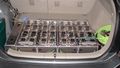
Install Battery Box
Install the Battery Box.
- Locate, drill, and press nut body/frame mountpoints
- Attach Electronics Box to bottom of lower battery box frame
- Install and fasten lower battery box frame
- Populate box with batteries
- Install battery regulators and interconnects
- Install and fasten upper battery box frame
Interlock Box
| General Disclaimer: (HV) (DC) injury or death hazard, use at your own risk, may void warranty. |
|---|
|
HV (High Voltage) DC (Direct Current) Warning: Traction Battery Packs, Motors, Chargers, and other HV sources could cause serious injury or death if proper precautions are not taken while working on or around such High Voltage Direct Current sources. Use this information at your own risk: There is no warranty expressed nor implied and we are not liable for any of your past, present, nor future actions. Even should you perform these modifications to the letter you could still damage any number of components in your vehicle causing it to no longer function. Even if it appears to function properly your actions may cause it to self destruct with collateral damage to surrounding properties other than your vehicle. By utilizing these ideas and instructions in an attempting to enhance national security, reduce gas consumption, vehicle "emissions", your carbon footprint, or smog, you do so at your own risk & peril. Warranty: In performing some of these modifications you may void your warranty with the vehicles manufacturer. See also our My wiki:General disclaimer |

The Interlock Box connects all the components of the kit. The low power signals from the CAN-View relays and other OEM systems signals enter the interlock box. These signals are then passed on to the charger to enable full power mode and two voltage settings, they can also enable full speed mode for the OEM battery cooling fan Y!:Prius OEM battery fan control info. The high power cables from the OEM battery, grid charge port, charger input, and charger output connect here. The box contains the high power contractors which switch from charge mode to PHEV mode. The PHEV battery pack inter-pack fuse or breaker as well as the AC line power circuit breaker are found in this box. The interlock box has been created as a 10" square plastic utility case, an aluminum box which fits the passenger side cubby compartment, and an aluminum rectangular box mounted near the charger in the universal modular battery box.
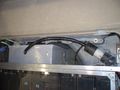
An early plastic box
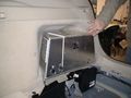
Fitted cubby area box
Modular box (far left)
Modular box with cover


Charge Port
- Bumper inlet charge port options:
- maillist discussion subject: Bumper Inlet Receptacle
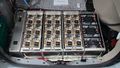
Regulators


The battery regulators monitor each 12v battery to make sure each is never over-charged nor over-discharged. During the charge cycle each regulator is capable of dissipating x watts of power as well as communicating to the charger in order to lower it's charge rate. During the discharge cycle each regulator communicates with the charger to lower it's discharge rate once a battery reaches about 10.5v under load to prevent them from being over discharged. This regulation system should protect and prolong the life of the battery pack as well as help to diagnose any issues that may arise with weak batteries. Digital versions of the regulators are also capable of communications with a computer over a serial RS232 bus to report their current state and to accept new parameters.
Drive and Enjoy
Charge, Drive, and Repeat...